PIMP - Pet(it) Interferometer Martin-Puplett
The PIMP is a compact Martin Puplett Interferometer (MPI) constructed in house by Institut Neel and IRAM. It was specifically designed to be able to perform measurements of the NIKA2 transmission directly at the telescope in complement to those performed at the lab with the Neel-LPSC MPI.
Quick installation guideline with photos
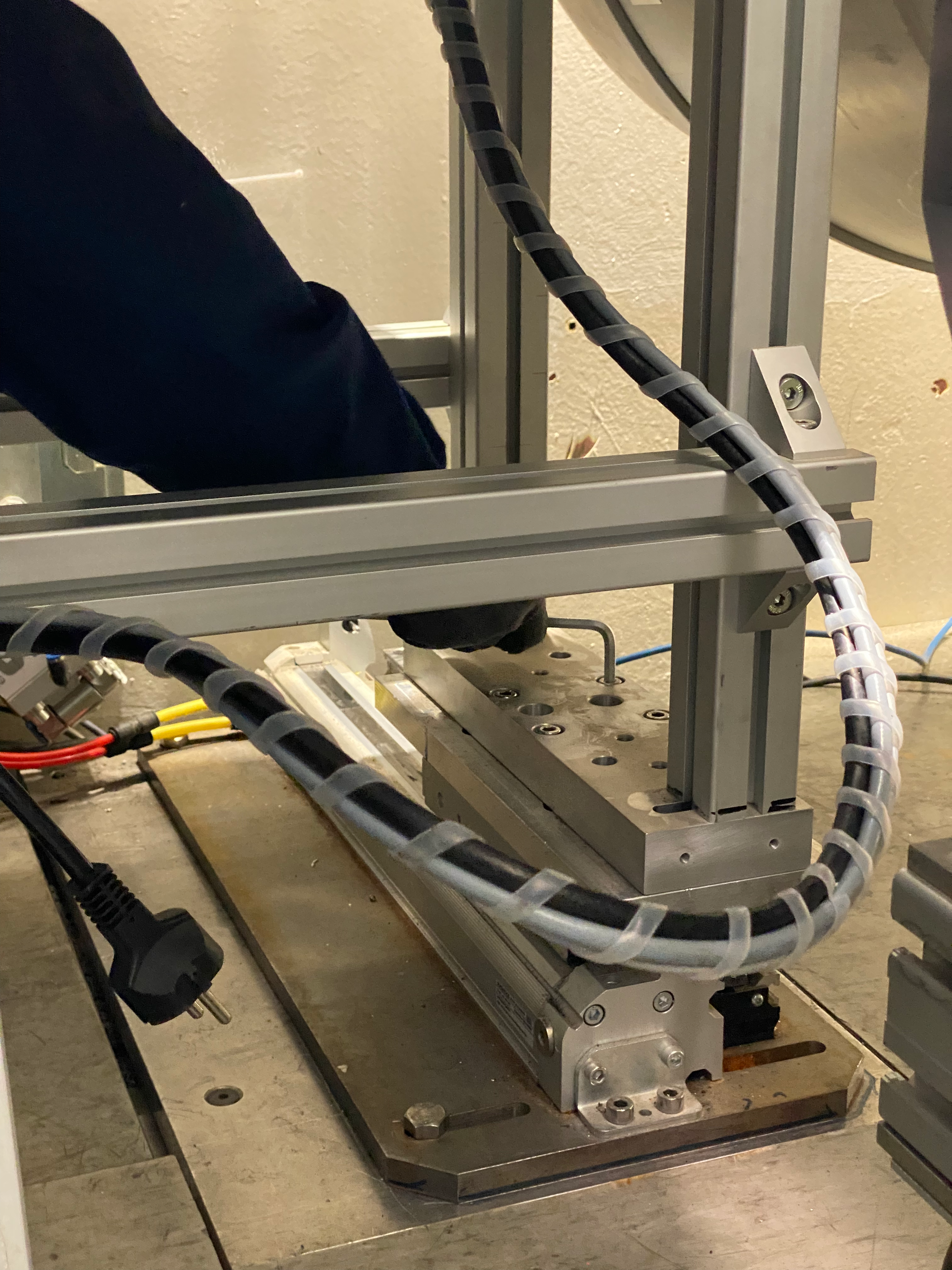
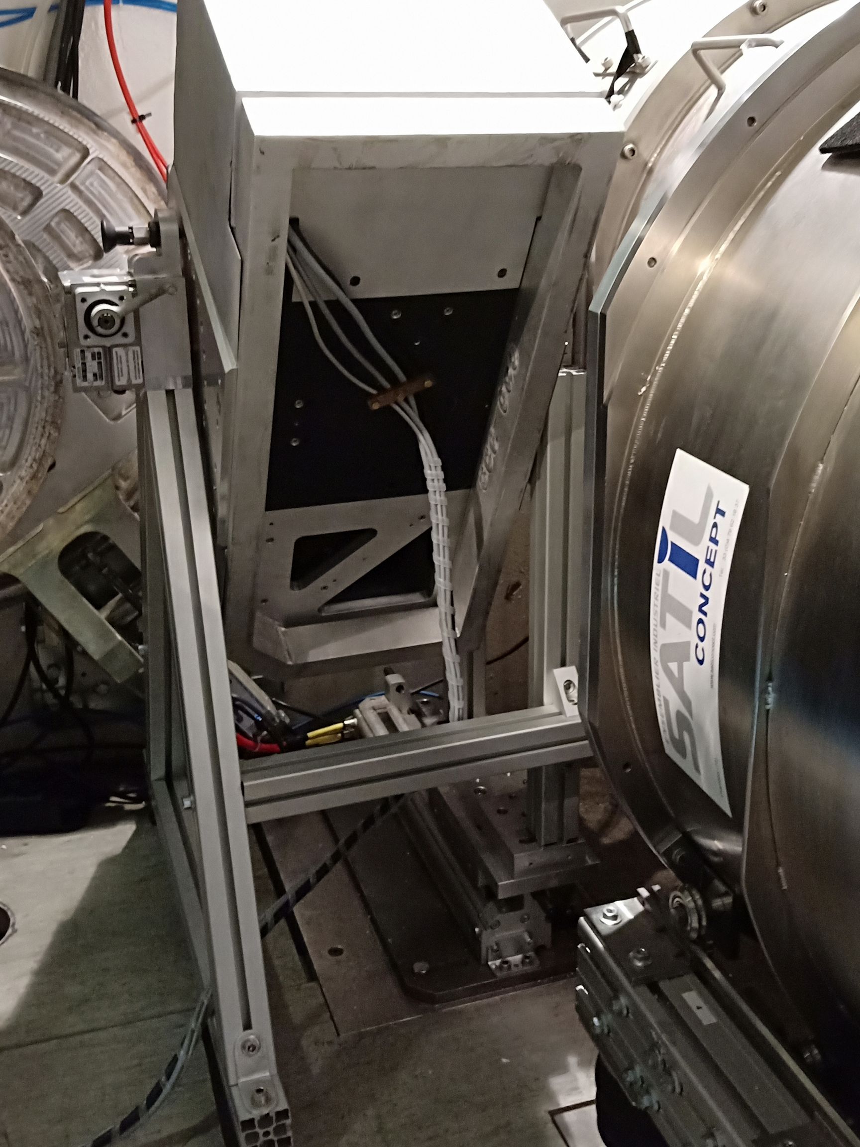
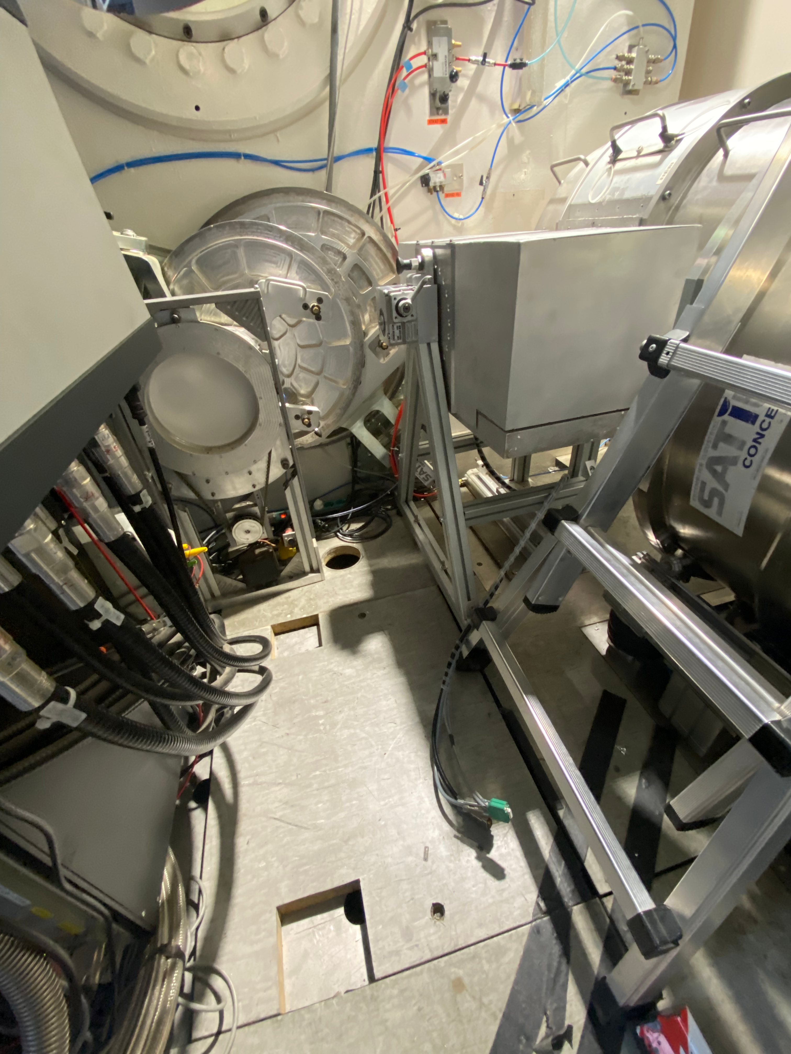
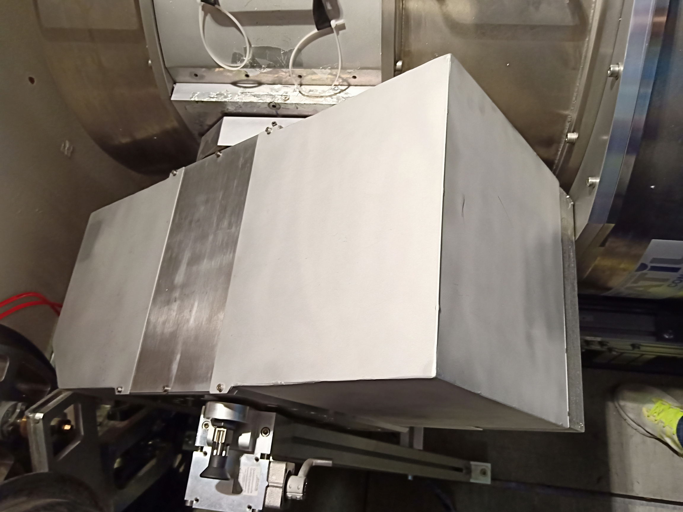
A couple of photos can help for the step-by-step installation of PIMP:
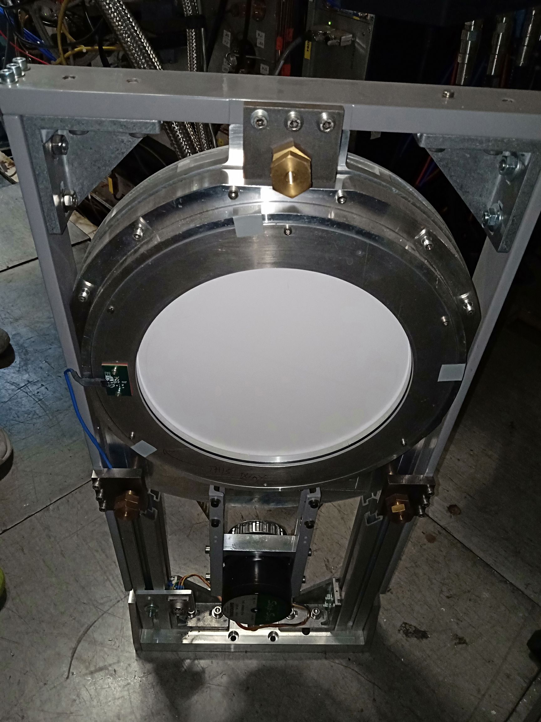
- HWP dismounted: so you can see which part of the HWP assembly has to be dismounted from ist rail system.
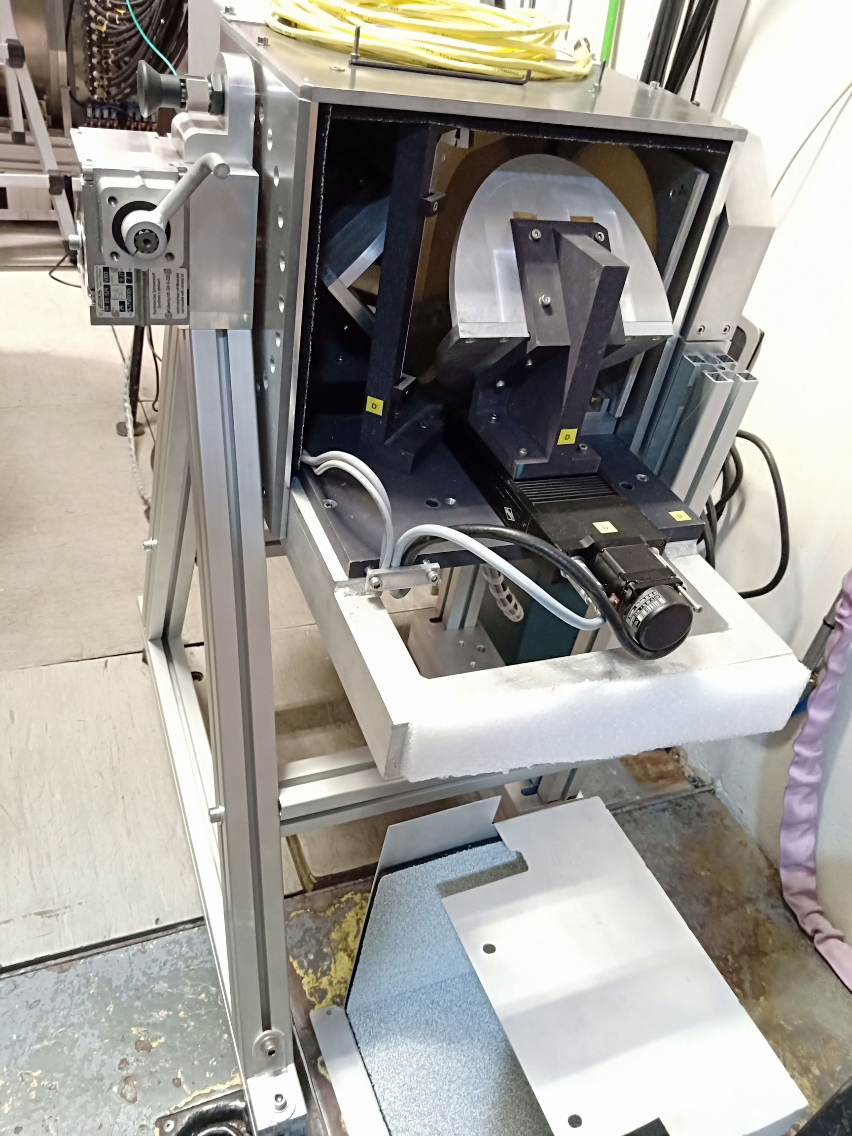
- PIMP on its frame with one cover removed, but not yet installed in front of NIKA2. The photo shows how frame and PIMP are assembled.
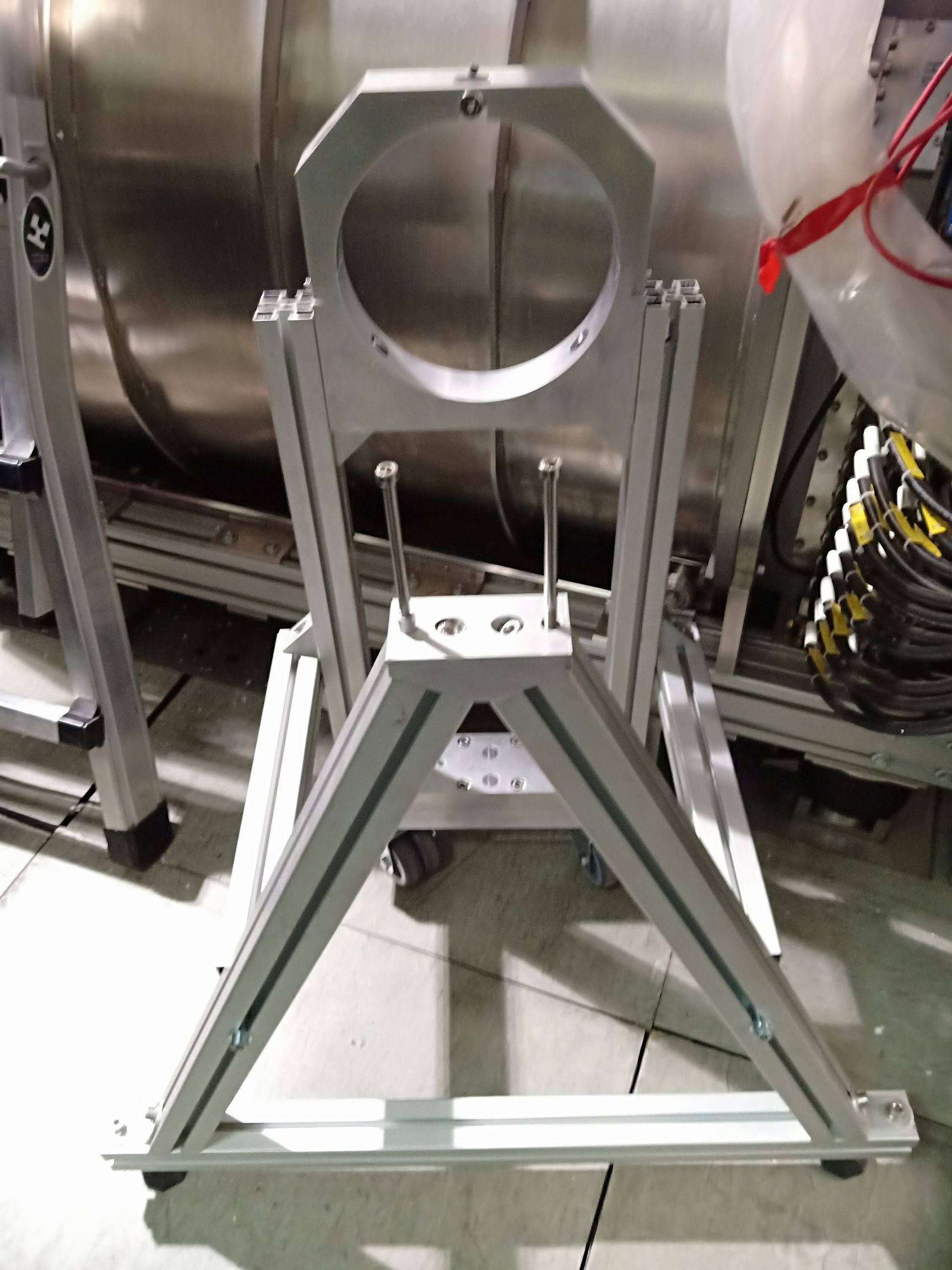
- PIMP frame: First install the frame attaching it to the ground plate where the HWP was before. Then place the PIMP main element on top. Just before putting the PIMP main element on the frame, remove the top half of the hole where the output optics of the PIMP has to be placed, then install the PIMP main element and put back the piece that forms the top half of the hole. On the opposite side, unscrew the long rods fist, then put them back once the PIMP main element is in place.
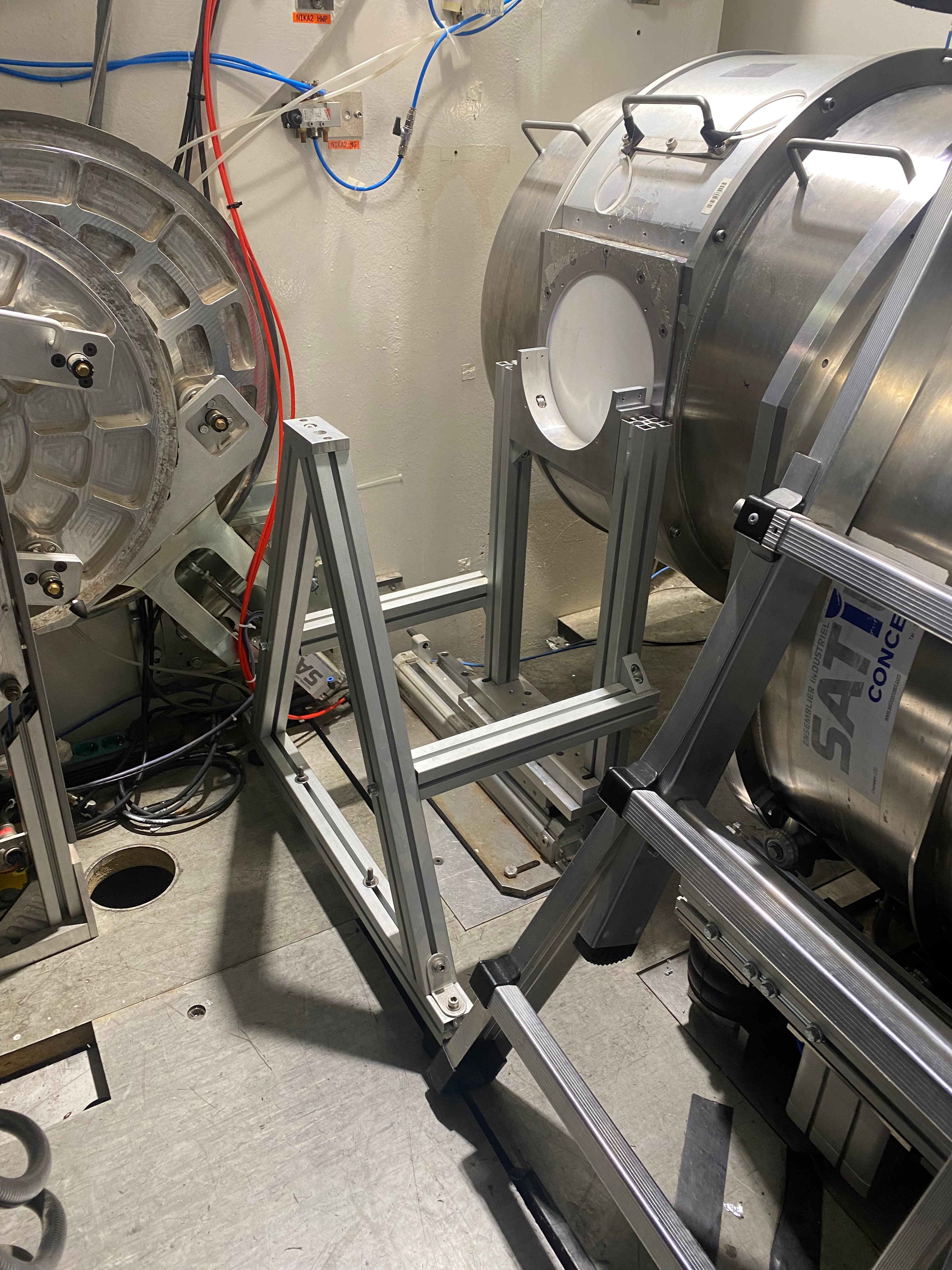
- PIMP installed for NIKA2: look in particular at the feet of the frame, how it is screwed to the piece that lies on the HWP rail system.
- PIMP NIKA2 minimal spacing: when its correctly installed, see how close is the PIMP output to the NIKA2 window, and the minimal spacing between PIMP frame and the NIKA2 piece making the interface between the cryostat nose and main body, when we rotate the PIMP.
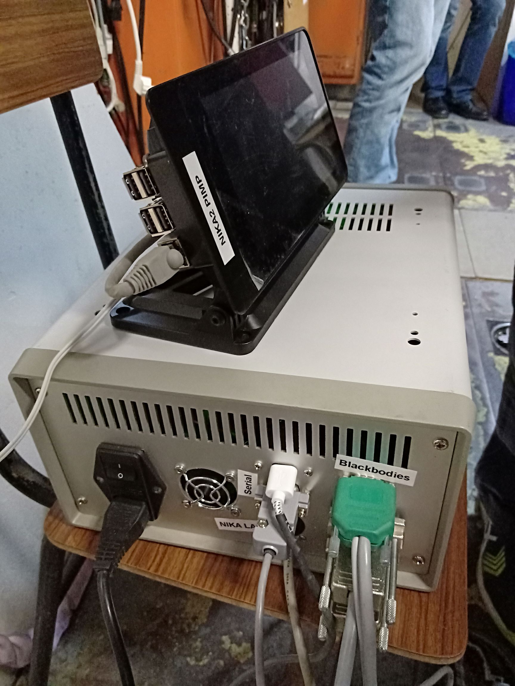
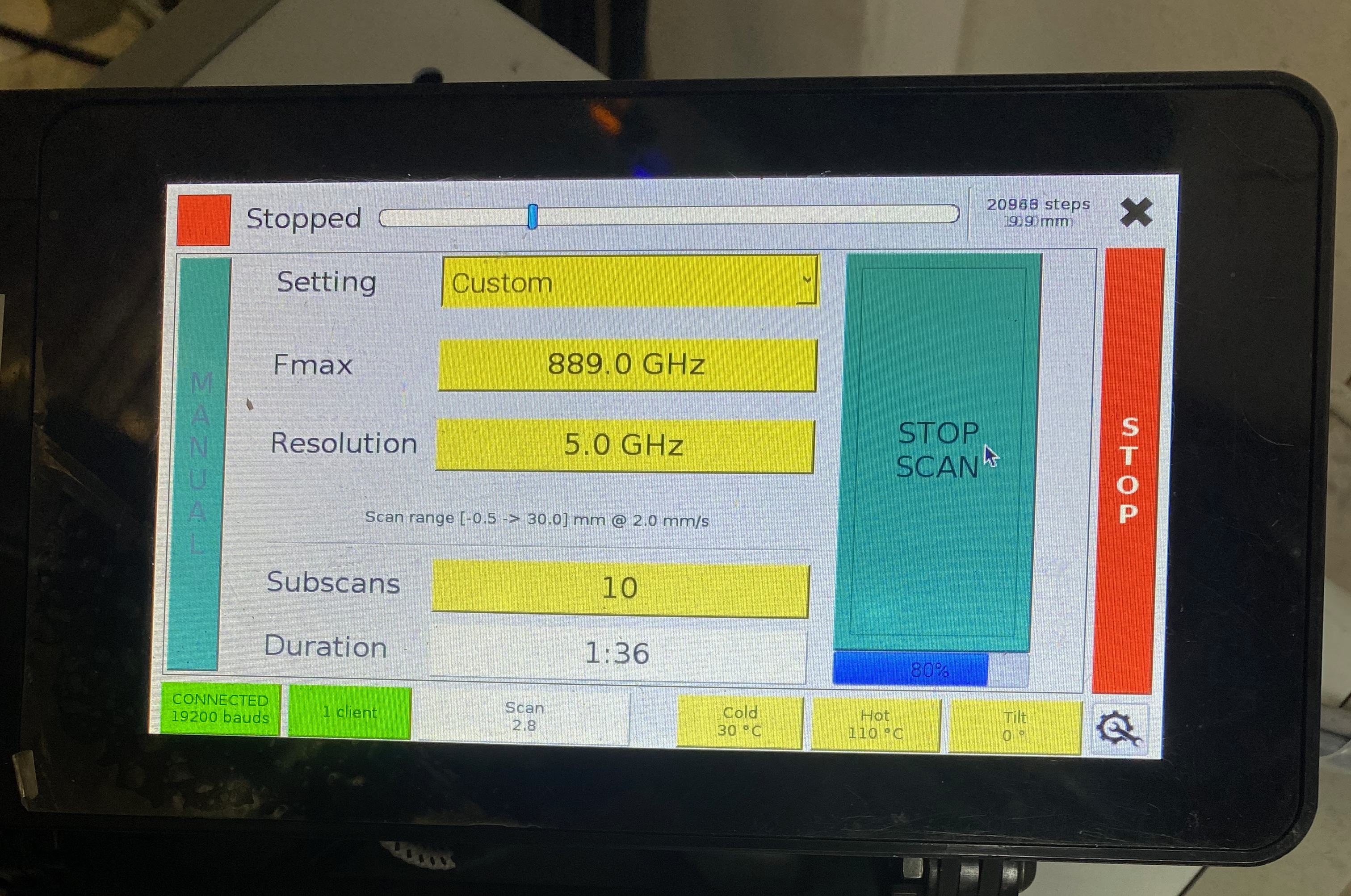
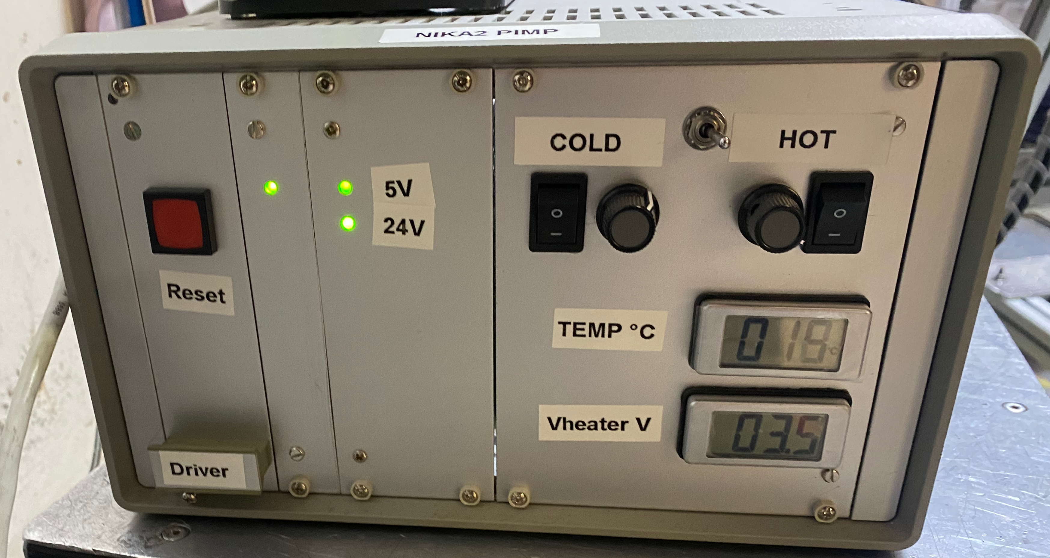
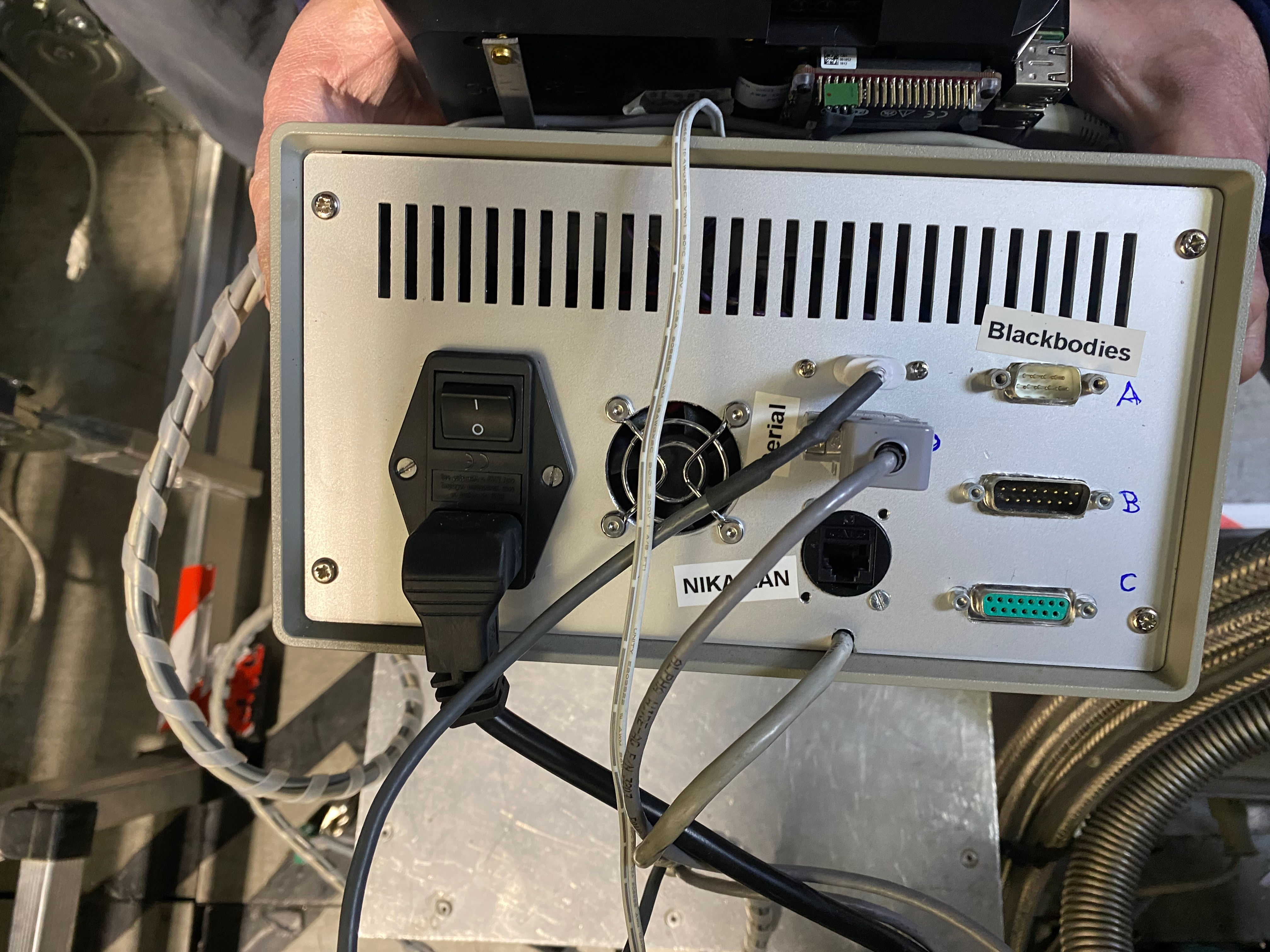
- PIMP electronics: Raspberry control unit and grey box Electronics plugged. Raspberry display. Grey box front view. Grey box back view (unplugged).
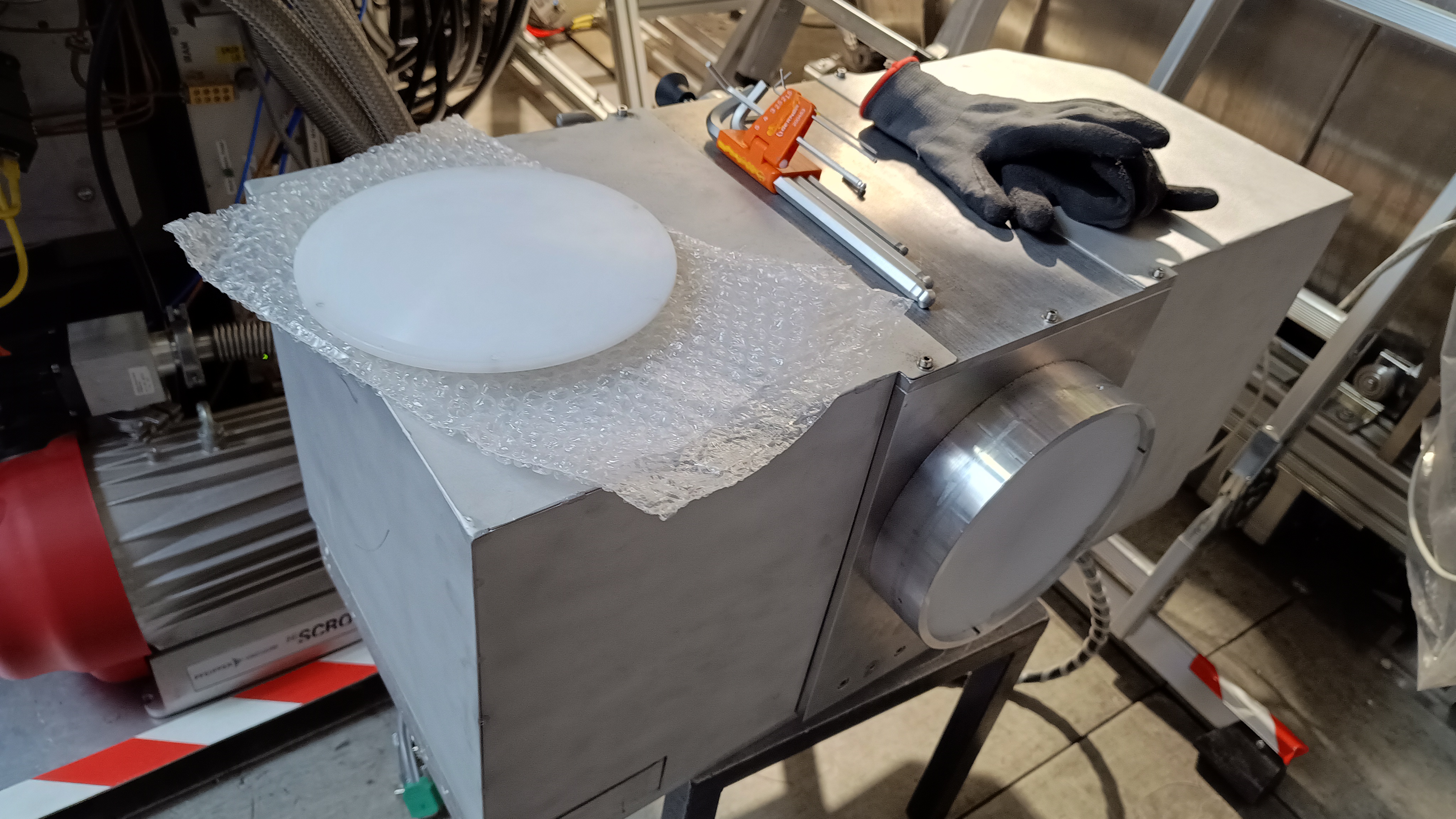
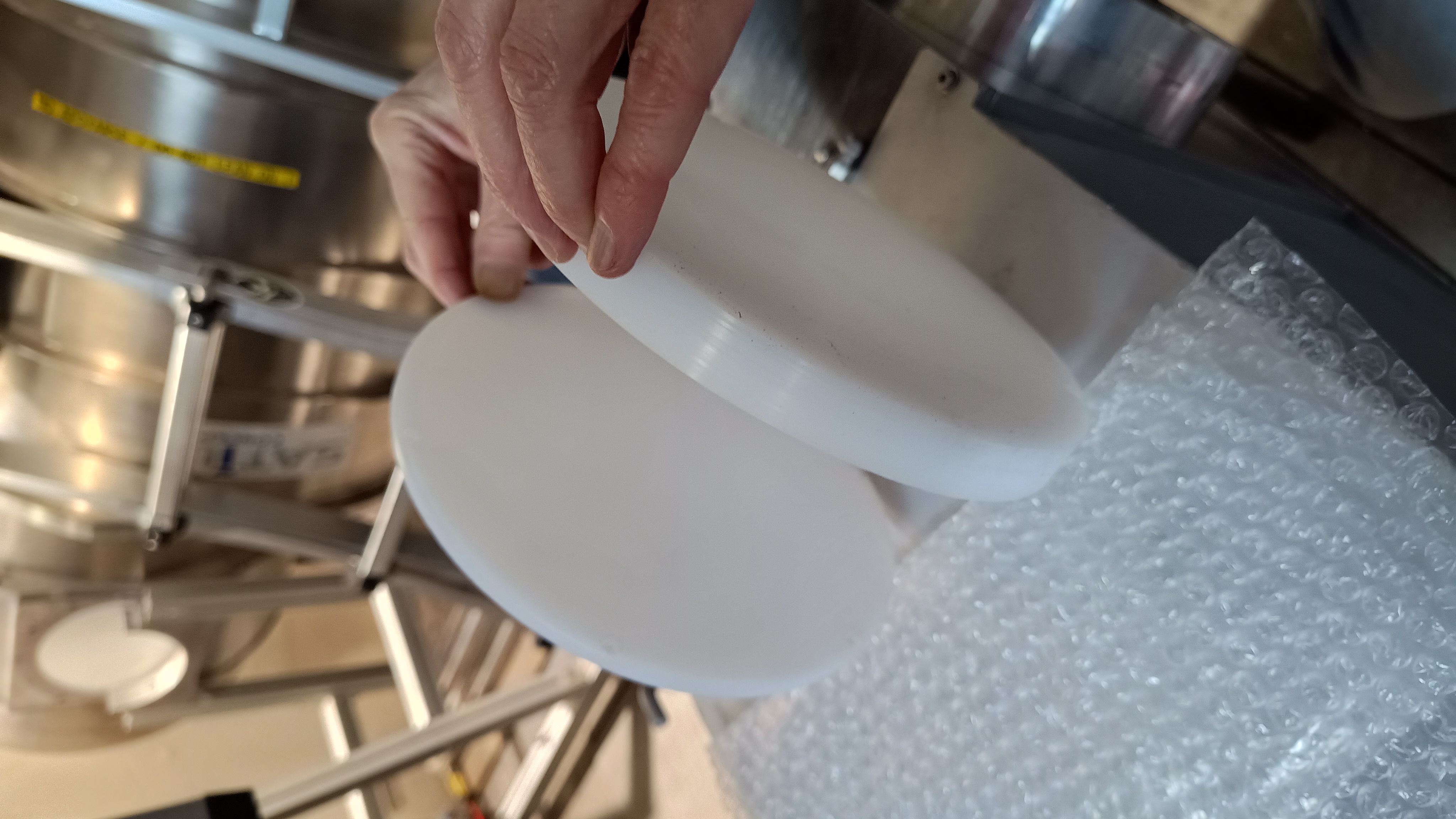
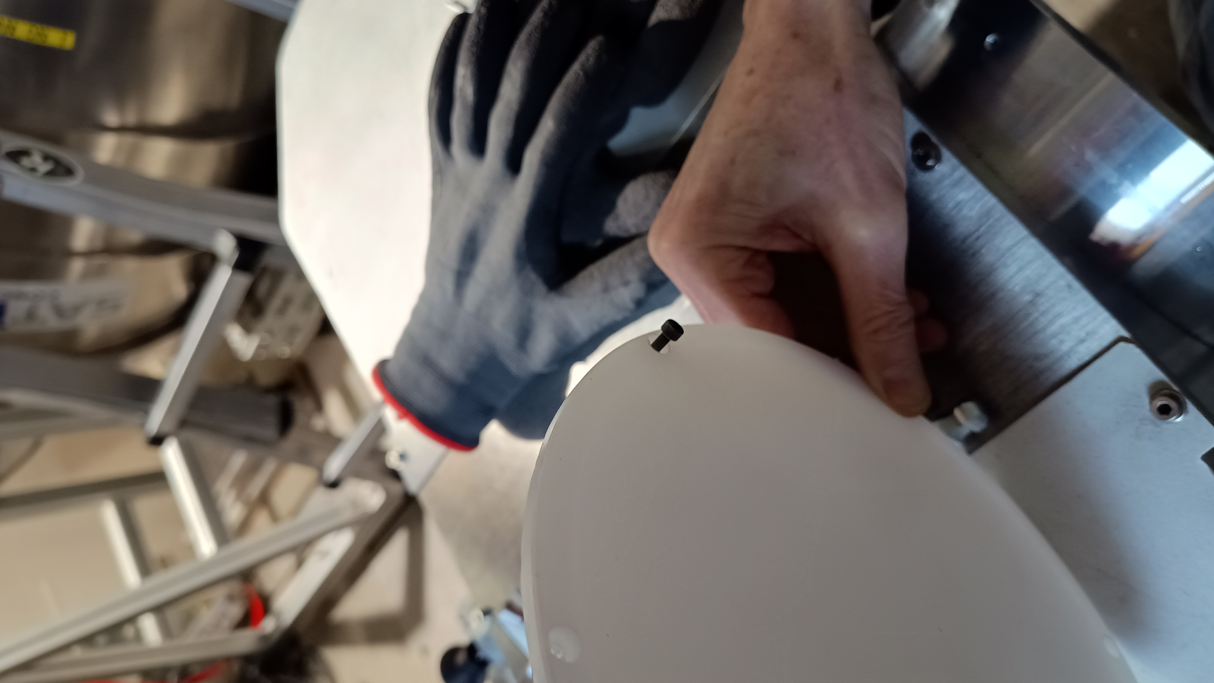
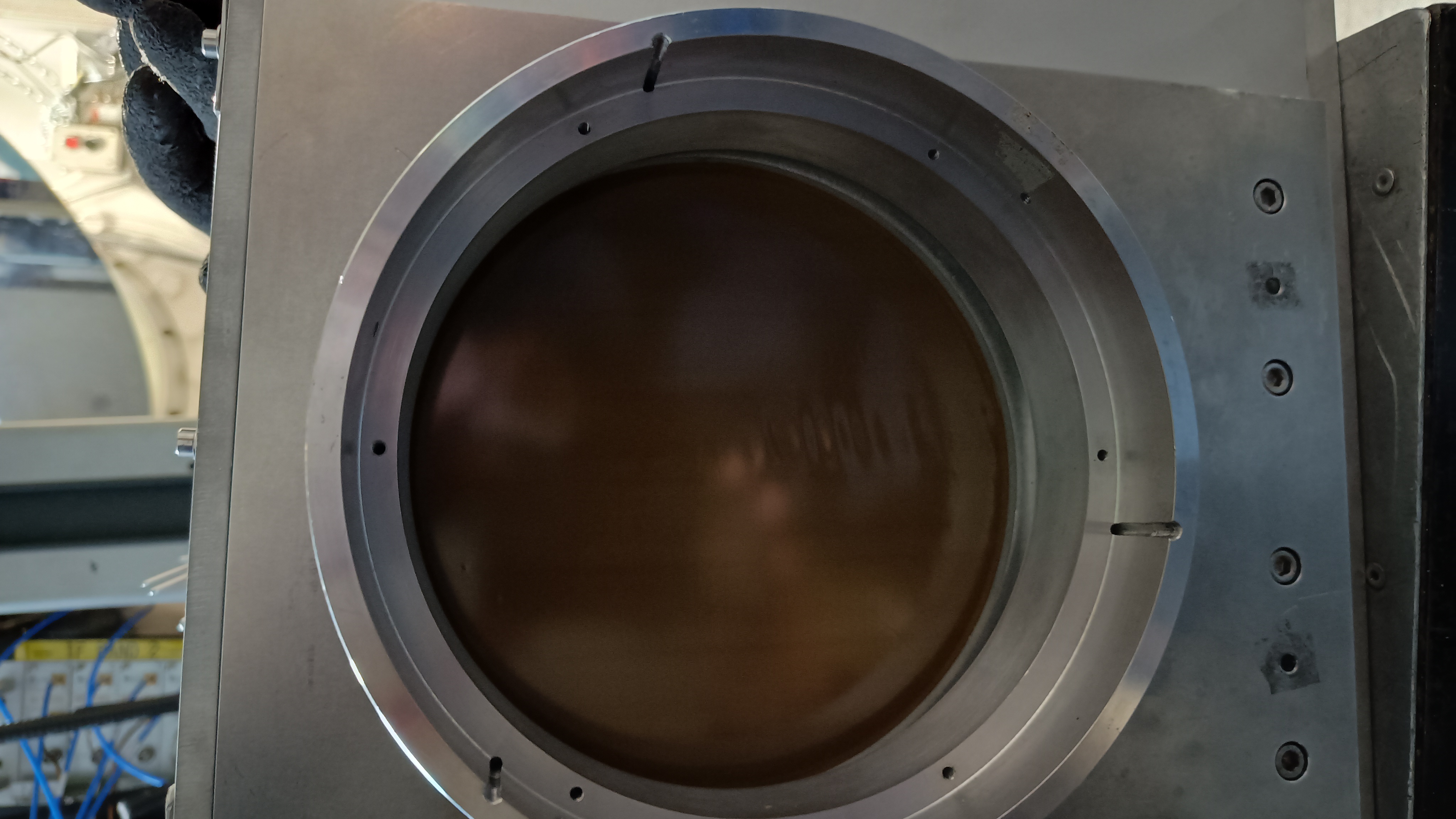
- PIMP external optics: A divergent and a convergent lens are available. The screws for the latter are shorter. The last picture shows the aspect of the PIMP window without external optics.
How to setup the PIMP with the acquisition
when the pimp is plugged on the NIKA2 network, it sends various kind of data to the network (scan start and stop, the speed, frequency and so on). These data can be read by the NIKA2 acquisition, providing that there's the correct variable declarations in the ini file. The Pimp is treated by the acquisition like an "instrument", exactly like each Nikel board is treated. If you look in the folder where the ini file are you will find 3 ini files that contain PIMP specific variable declarations. You will have to use them. If you are not so sure about these ini file you can have help from Juan, Martino, and Alessandro.
Measurements of the NIKA2 bandpasses
2018, 2019 campaigns
Two campaigns were performed in summer 2018 and 2019. Different angles of the PIMP polarizer with respect to the NIKA2 polarization reference frame were explored. Overall it was found that the NIKA2 bandpasses reconstructed with the PIMP are fully consistent with those measured previously in the lab at Neel. As of Jan-2025 and in preparation of the NIKA2 upgrade in March 2025, a report has been drafted by J.Macias-Perez, A.Bideau, S.Leclercq, A.Monfardini.
The measurements in 2019 were done as follows (taken from the daily report): Cold black body at 30°, hot black body at 110°. Need to set PIMP control at 19200 bauds in order to get the interferograms (I or Q vs position) in the acquisition software trace screen. WE set Fmax to 892 GHz and the resolution to 5 GHz. Two series of measurements were done: 7 scans per series, 10 subscans per scan. Series 1 was done with the convergent lens at the output of the PIMP, series 2 was done with the divergent lens at the output of the PIMP ; each of the 7 scans per series is done at a different tilt angle of the PIMP: 270°, 300°, 330°, 0°, 30°, 60°, 90°.
March 2025 campaign
After some iterations, the Raspberry was setup with the following parameters:
Parameter
Value
Homing speed
112 step/s = 4.464 mm/s
Sampling freq
46.4 Hz
Zero path
100 steps = 0.05 mm
min lim
0 steps = -0.5 mm
max lim
78200 = 38.6 mm
Short step
1000 = 0.5 mm
Initial speed
119 step/s = 0.059 mm/s
Initial acc
255 step/s2 = 0.128 mm/s2
Fmax
892 GHz -> 891 GHz
resolution
3.9 GHz !!
corresponding range
-0.5 to 38.5 mm
nr subscans
20
duration
3m46s
- Relative to the 2018/19 runs, the frequency resolution was reduced. At 5 GHz, the inner part of the fringe patterns stayed flat because the MP does not reach its maximum position. On the other hand, chosing 3.9 GHz, the MP reaches the maximum range and the fringe patterns are nicely seen.
We also lowered the hot load temperature to <70 deg. This way almost all KIDs of Array 3 could be tuned.
- Other comments:
- Temperature for the cold and hot loads have to be set by hand in the frontplate of the grey box by setting voltages and then entering them by hand in the Raspberry surface.
- When preparing for observations: the connection to the DAQ should be active. Listening for clients on IP 192.168.1.245, port 1234.
- DAQ should use run84_pimp.ini . It sets e.g. the KID sampling frequency to 47Hz.
- To start recording a scan in the DAQ, click on the big black rectangle in the lower part of the small "file" window (usually on the same window where DAQ is launched); the DAQ a scan is started by clicking on the rectangle in the file terminal. It provides a file name. In the Raspberry then click on Start. To stop data acquisition in the DAQ click again on the rectangle.
Anyway we took data at different PIMP angles (-90 to +15deg). Angles >15deg are impossible, as the PIMP touches the cryostat.
- Autotuning should be switched off during a scan.
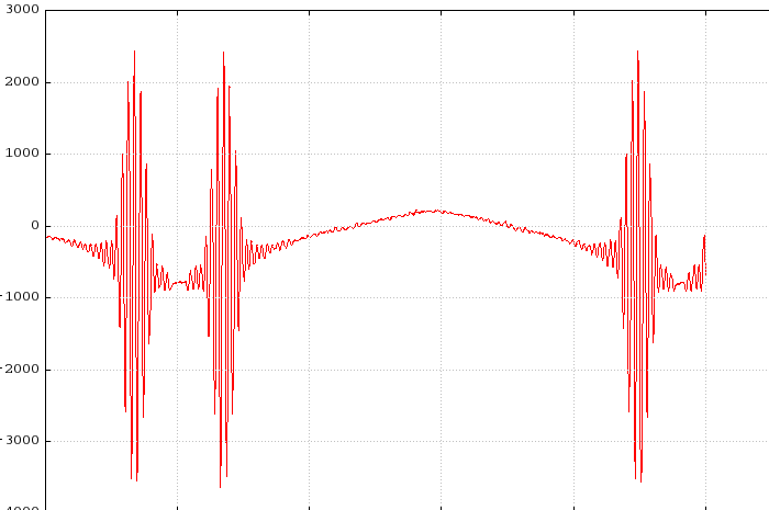
- We examine the traces on the DAQ and we clearly see the fringe pattern, both in the time lines and when plotting against position.
The Raspberry scan parameters are probably sent to the DAQ to be included in the file scan headers.
Details of the March 2025 campaign are found in the Daily Reports: https://publicwiki.iram.es/DailyReportsNika2Run72
- Screenshot of a DAQ timeline showing Interferograms
- Open Questions: to what accuracy does the PIMP need to be levelled ? Why cannot we now rotate the PIMP beyond +15deg, while in 2019 it was possible ? Why do we now need to put the resolution to 3.9 GHz and 5 GHz don't work as in 2019 ?
Appendix
NIKA2 bandpasses before the upgrade of 3/2025
https://publicwiki.iram.es/SpectralBands based on measurements in the Neel Lab.
Draft report of the 2018/19 PIMP/NIKA2 campaigns: macias-perez-jan2025-v0-draft-NIKA2_PIMP_Results.pdf
Documentation on wiki.iram.fr
Some documentation on PIMP is available in the NIKA2 private wiki documentation page. See
- Original specifications document containting some drawing giving an idea on how the frame is mounted on the HWP pedestal.
- Control computer documentation is the document written by Aurélien Bideaud explaining how to start and control the PIMP. It is already printed at the telescope, on the NIKA2 table in control room, and in the PIMP box. You can skipp the first part on the Raspberry and start ready from User Manual on page 5.
- Purpose and optics simulations is a presentations SL had prepared almost 6 years ago but never showed, because SL wanted to combine its presentation with presentation of the results from Juan. It explains very quickly the purpose of the PIMP in the main lines, and based on Zemax simulations explains the purpose of the convergent lens and the divergent lens you will find in the PIMP box.
- Video and photos showing the start of a PIMP scan and pictures with different orientation of the PIMP (once the PIMP is installed, use the crank handle on the side opposite to the cryostat to rotate it, and the pin break to maintain id at a given orientation)
Daily reports wiki pages of measuring campaigns
1/2025: https://publicwiki.iram.es/DailyReportsNika2Pool140125 (Only testing functionality in the 30m lab)
Created: 2025.Mar.20 created by CK, initially based on various mails from SL.

