Back to the NIKA2 main page
Back to NIKA2 run 72 (Cryo run 84) main page
Contents
Discussion about Run 72 online results: explanations on various features
During the Run 72, recommissioning of NIKA2 after upgrade, several actions and online results triggered emails exchanges to understand various features. As mails involved a restrained number of persons, and get lost after a while, I gather here the exchanges that produced information that could be useful to keep at hand for later.
PIMP
Nothing more to report that hasn't been already written in the Daily Reports and dedicated special PIMP page. Outcome: 1 mm bandwidths significantly increased with respect to situation before upgrade => positive effect on 1mm sensitivities (among other positive effects, in particular dichroic and KID arrays designs)
Mails from the "Daily zoom meeting (NIKA2 re-commissioning)" thread
Most of the emails exchanges are reproduced, not only the final explanation, because even the investigation path contains interesting information.
Introduction: preliminary results and possible problems from the 1st series of commissioning scans on sky
Stefano's 1st mail of the thread 25/03/2025:
We have performed quite few observations yesterday/today. We have filled the daily report with some analysis of the beam-maps and some focus statistics (very preliminary). We have also tested the Box C board, which does not seem to be the culprit of the noisy Box. Our gut feelings:
- Ar2 has definitely some problems, with this Box C much more noisy (and therefore rejected by the data reduction).
- The reference KID (central KID of Ar2) belongs to Box C and there seem to be no way to recover it.
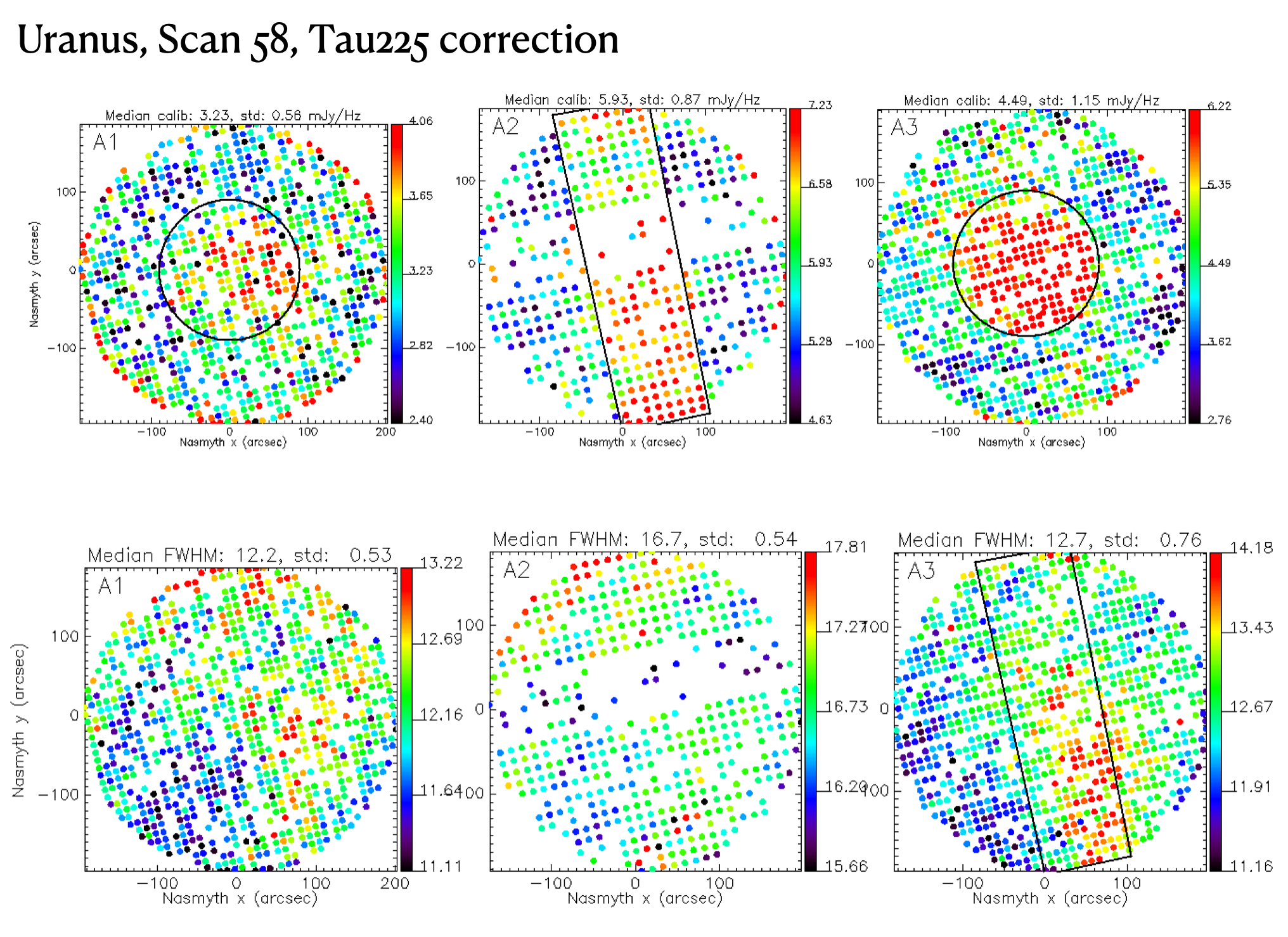
- the flat field of Ar3 looks sub-optimal, with a very bright light concentration in the center
- the flat field of Ar2 is similar to before the upgrade
- the flat field of Ar1 is very much improved
- the focus of Ar3 seems to differ by 0.2 mm with respect to Ar1 and Ar2, but we have only data with mediocre/bad 1.2 mm focus sequences at the moment (i.e. not good at 1.2 mm).
- The Ar3 focused beam looks also worse than the Ar1, and might show a stronger astigmatism
Nico 25/03:
Calibration and FWHM plots that illustrate some of Stefano's descriptions:
Samuel 25/03:
On the good news side, in additions to the ones already mentioned (all lines alive, high good KID yield, large bandwidths, good preliminary S/N, no more gradient), I see that not only the crippling problem we had in 2015 with the dichroic 1 for the A2 channel has disappeared, but from the preliminary foci the residual distortion of this dichroic looks now even lower than my expectations from the lab tests with the new mount. This is most probably due to a better thermal environment generating a lower temperature gradient across the membrane. At this stage there's no clear evidence that a reopening for arrays shift is necessary. We need better focus statistics on good sky to figure it out. On the bad news side: see sections below.
Noisy Box C on Array 2
Samuel 25/03:
On the bad news side the most obvious is the problem of line C on A2. The test you did at 1:20 last night, using a NIKEL spare board in place of the one that was in box C seems to rule out the warm electronics indeed. I was wondering whether the problem could be a bad connection between the Array holder and the semi-rigid cables, but I see from the pictures of the upgrade that we never touched the connectors of A2, as the dark KIDs we removed were plugged only on A1 & A3 lines. Since we actually touched nothing on the A2 circuitry, I'm really puzzled by the appearance of this strong extra noise on line C. Alessandro, Martino, is there a way to test electrically the line by sections, doing on one side the cryostat part and on the other side the warm sections; input, then output ? And what about the cold amplifier?

Alessandro 25/03:
I am extremely worried for the 2mm box C.
I would check if the cold amplifier is correctly polarized (tensions on stages, current etc.). In any case the cryostat should stay cold until the problem is understood. In case we might ask you to have a look with a VNA, disconnecting the N connectors corresponding to box C and having a look. But first of all I would like to try connecting.
Dave 25/03:
Ch7 of the 2mm pre amp reads:
set point 5.0 volts, Vd(v)2.3V, Id 0.01 mA. !!
Channels 13-16 id 0.01 mA.
Ch7 still stays at 0.01 mA despite a switch on - off
Looks like a problem.
Alessandro 25/03:
Yes I confirm that the channel 7 (first stage of box C corresponding cold amplifier) looks dead. The ADC value on box C is 2% only, explaining the noise that is 50Hz/sqrt(Hz) instead of 1Hz/sqrt(Hz). Incredible our KID are still seeing Uranus in these conditions. Not worth connecting a VNA, the problem is now clear and doesn't seem to be related to the array (the KID are all there and responding, just with more noise). Really annoying.
I have tried to reduce the attenuation on the output side (can go up to 15% on ADC) but it doesn't seem to be helping a lot. Clearly without the first stage of amplification something is going through in some way but very noisy.
Two options: a) the amplifier is broken; b) the (blue) polarisation box has problems on channel 7. Of course I would prefer the b) option.
I think there should be a spare of the custom (made in Néel but discontinued now) polarisation box in the spiral room. I am not saying it's easy, but in principle the hypothesis b) could be tested, if you keep the cryostat cold long enough.
In any case life goes on with the other 15 lines. Thanks for your analysis efforts and patience during bad weather, and skill/promptness in observing immediately when conditions barely allowed. Please extend my gratitude to the Granada staff that is not in CC.
On top of the "C-box-catastrophe", we had already seen during the sweeps (and confirmed by your plots, it seems) that the box S (on array 3) is also noisier.
This might well be intrinsic in the array. To be investigated.
Alessandro 2/04:
(this follow up is extracted from 2/04 NIKA2 regular meeting) Found at Pico and Neel spare amplifiers that could be used to change the one broken on Array 2 line C (see last week minutes). The change requires opening the NIKA2 cryostat from the back, no need to open all screens. Main suspect for the defective line C is the amplifier, but there's also a secondary suspect which is a connection problem on one wire inside the cryostat. So if needed in Neel we also have spare amplifier requiring less wires. Monitoring the amplifier current during warm up could be interesting. We need a VNA to test the amplifier after having mounted one of them in the cryostat.
Note that the kind of cold amplifiers we uses (ONLY FOR 2MM !!) are known from lab experience to have a significant chance to break after many full thermal cycling (Ambient T <-> Cold T), in general due to thermal stress on a wire bonding inside the amp box. There's 4 such cold amplifiers in NIKA2, the fact that one broke after so many years and cyclings is not that surprising. The full warm up plus displacement of NIKA2 for the upgrade was maybe the little kick that finished it off, but is in no way the upgrading team's fault who touched nothing along line C. So we can just consider this loss as coincidence. Alessandro: careful, for the 1mm is totally different amplifiers.
We can also find commercial amplifiers compatible with specifications for Array 2, such as this one from Low Noise Factory: https://lownoisefactory.com/wp-content/uploads/2023/03/lnf-lnc0-6_2a.pdf
Array 3 strange central part in the flat field
Samuel 25-26/03:
The other element on the bad news side is the strange excess warm spot at the center of A3 ; this looks like and optical effect, but as A3 is all in transmission. So, the problem is visibly not on any element before A3 itself. It really looks like it's the central KIDs themselves which have a different response than the others. Could it be a problem of Al deposit? Did you notice such an effect in the lab Alessandro and Martino? ... Unless there is a polarised parasite along the optical line? I which case, if it is outside the cryostat, placing the HWP in front of the window would change this effect. (...)
Now if A1 sees it also even at a lower level (see Nico's calibration plot), then the chances that it's something in their common optical path is now more likely than an array problem... though it could still be an array "problem".
Since the preliminary sensitivities on this zone seem still quite good and almost not affected compared to other parts, it means the element causing this effect is not something more or less opaque, blocking rays coming from the sky, and it's not something fluctuating creating some excess noise. So the first idea that comes, if it's caused by an optical element, is a background excess, in other word a zone where the temperature is slightly higher than elsewhere, on a gray body element. All the optical elements that don't have exactly 100% transmission are kind of gray bodies.
1 mm wavelengths are emitted by bodies which have a temperature >1K. The new elements we introduced are the dichroic, and the AR lenses in front of A1 and A3.
I can image a possible thermal gradient on these elements, but:
(1) why such a sharp transition between the central zone and the rest rather than a continuous change?
(2) if the center of one of these elements is >1K (while the edges must be close to 150 mK), wouldn't it put too much stress on the dilution system?
(3) if it's the dichroic, why don't we see it on A2?
(4) if it's the AR lenses, why don't we see it also on A2 which also has an AR lens in front of it, and why wasn't it not present with the smooth lenses that are made with exactly the same material?
(5) is it possible that it was present before but not visible because the previous arrays were less sensitive?
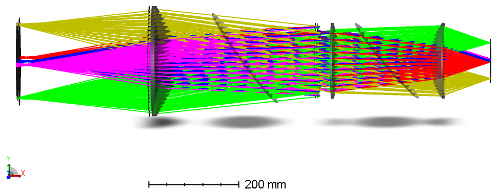
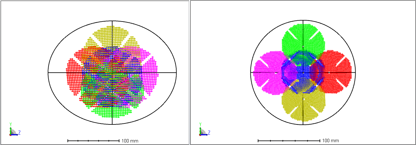
In terme of illumination here are some screen shots from Zemax simulation showing rays from a point source on the optical axis (blue) and from the min and maw Az and El positions of the FOV (other colours): 1) a profile view from the field stop to A3 ; 2) a layout of the dichroic ; 3) a layout of the AR lens in front of A3. You can see how each point on the the array "sees" each of these elements (e.g. the central pixel sees only the central zone covering ~1/3rd of the AR lens)
Alessandro 25-26/03:
I don't know. If it was the array I would expect the opposite. The first resonances are in the middle so in principle they should have less noise and less response. Also supposing a thicker Al film the response should go down. (...)
Sorry my mistake. The plot was Jy/Hz and not the opposite as we do usually in lab ! So it could very easily be the array, since I put the lowest frequencies in the middle by design. The sensitivity is flat so less response and less noise, as expected.
Samuel 26/03:
Just for the information of the others who might not know exactly what we're talking about: the flat field calibration factor gives how many incident flux (Jy) you need to make the resonance move by 1 Hz, so the higher the value, the lower responsive the KID is. And now, Alessandro just explained basically that the arrays are made like that by design.
And as you can see on the preliminary sensitivity plots from Nico, this is not really a problem since what matters is not the response alone but the signal to noise ratio of the detector.
Note that when we see some special features like that on arrays maps, where there's a very sharp transition from one zone to another (here for example you have pixels in red in an inner circle, and just at the border out of the circle the pixels drop drastically to a blueish colour), then you can be sure this is not caused by the optics in front of it. Indeed, remember the figures I sent yesterday: each pixel of the KID array sees a large fraction of the optical elements (lens, dichroic...) so they can't cause a sharp changes of any quantity between neighbour pixels, they can only create smooth transitions over many pixels.
Radio alignment
Samuel 31/03:
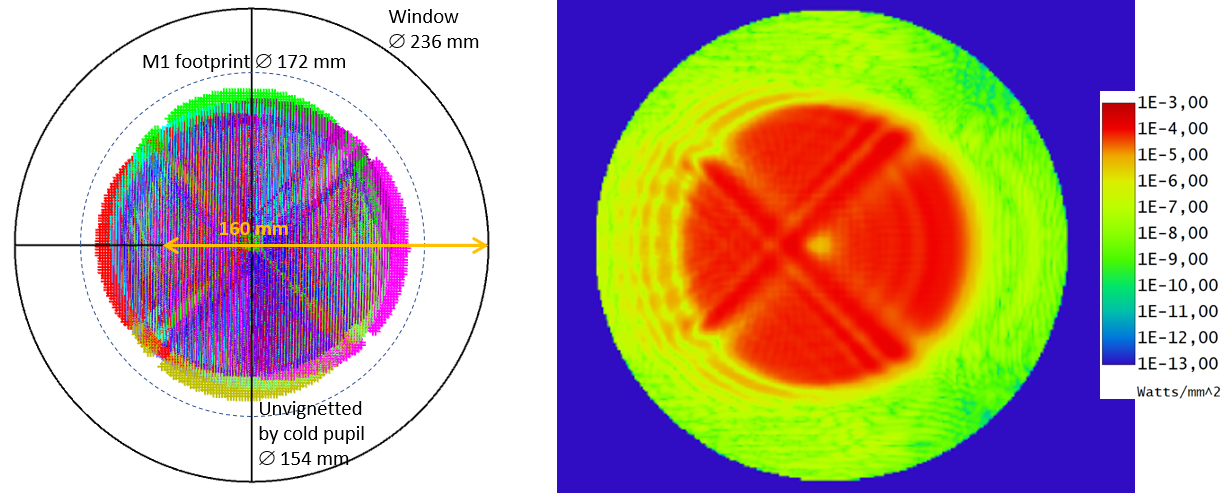
I'm surprised by your results (Daily report, March 30), the sensitive area should have been much bigger than that. Unlike the measurements done in 2017 (see the History_of_optical_and_radio_alignments_of_NIKA2.pdf which is also available at the beginning of the "Commissioning & special test runs" section of the main wiki page), your measurement don't seem compatible with the expectations from optics simulations. Indeed as you can see on the figures below, in terms of rays tracing (left figure, showing the footprint of 10 beams from various point sources across the FOV) you should have a circular sensitive area (your 45 deg measurement actually go in that direction) of ~15.5 cm diameter, and in terms of physical optics propagation (POP) (right figure, showing the beam from a point source at the FOV center in a log-10 scale), which accounts for diffraction effects all along the optical chain, the sensitive area should even be a bit bigger, reaching almost 20 cm diameter. The POP figures illustrates why it is important to oversize the window with respect to the ray tracing: the goal is that the warm spillover diffracting on the window edge is far enough from the useful zone that only the 10-10 side lobe level reaches it and thus has a negligible contribution to the background. Note that with radio axis determination using the Eccosorb you shouldn't have the asymmetry visible on the POP figure; this asymmetry is only for beams coming from sky and is due to the off-axis reflections on M5 and M6, it fades away and on focal surfaces and become lower than 10-3, visible only beyond the 3rd diffraction ring.
I don't know whether the too small size of the responsive zone you have determined is a real problem or is it just because the measurement is really not easy to do. At least you found it pretty well centred, with a (3,2) mm offset that seems acceptable. I'm a bit puzzled. For now I don't find any good suggestion on how to proceed with this radio alignment...
Stefano 31/03:
The solution was trivial, as a matter of fact, but it was at the same time not so obvious. Yesterday we did not use the most appropriate KIDs for this job. Today we realised that the most extreme edge KIDs need to be used. Therefore we repeated the "exercise" and the results are on the usual Daily report:
- Alignment not perfectly centered, but a bit shifted to bottom-left. I don;t know how significant, though, given the uncertainties.
- Size of the "active" region 18.2x19.2 cm
Samuel 1/04:
The new values you found are much more in agreement with the expectations. That's good, thank you for your perseverance! I'm still a bit puzzled by the 1st try on Sunday. As you can see from the ray tracing, comparing the extreme fields the zone where signal pops up should always be bigger and vary by only few cm. Namely, from the opposite window edge, the variation should be between 17.5 cm and 19.5 cm at most depending on the KID taken for the measurement. Anyway, at least the measurements you did yesterday are consistent with these values, given the uncertainties.
To get the radio misalignment you need to compare the position of the center of the cold pupil, that you measured with this Ecosorb technique, to the telescope pupil which is centred on the optical axis, that is to say the laser. In the window coordinate system x along horizontal, and y along vertical:
- apparently you found the following decenter for the cold pupil: (0, -2) mm
- while with the laser we had (0, +1) mm.
So we might have 3 mm offset... But with an uncertainty of what? ± 2mm? Tomorrow I will check the effect on the M1 illumination of a 3 mm mismatch. Maybe it's good enough like that, or maybe a slight movement of M6 (or M5) might help aligning both axes, and reduce a bit the spill over.
Stefano 1/04:
- as said in the previous email, in the Sunday morning radio alignment check attempt we were using a random box, i.e. we were doing it wrong. Yesterday we did it right. Nothing more than this.
- Yes, the previous measurement gave an off-center top-left, and now we found off-center bottom-left. Dave made the proper calculation and can give you the actual numbers. It does not seem to be only shifted down, but also to the left.
- BTW there's no way that the precision of this measurement is 1 mm, as said in the "history" document. It is at best 0.5 cm, or even 1 cm. The 1 mm is probably simply the smallest length one can appreciate on the ruler, but there are many more sources of uncertainty in this procedure (see daily report for some brief description).
Samuel 2/04:
- I agree that 1mm is just the reading uncertainty, and that other factors increase the global uncertainty budget. Still, I think that with a careful operation in very stable conditions it should be possible to reach 4 mm uncertainty (+/- 2 mm), or even better. But to do that one needs to have the acquisition running in the cabin on a laptop, so that the person doing the experiment can check in real time the reaction of the KIDs. And ideally the Ecosorb should be mounted on a sliding rail that someone could translate at least with a crank handle, or with a step motor (building such a device could be a small project in itself).
- I check optical and radio alignments variations in Zemax.
It turn out that in fact having the optical alignment 1 mm too high on the window is optimal!! So currently we are perfect with the optical... But only if the radio is optimal...
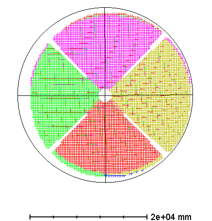
Concerning the radio, an offset of 3 mm downward of the M7-M8 assembly creates a 2 mm shift downward of the response zone on the Window, and a defect of illumination of the primary which is at the limit of acceptability as you can see on the left figure below. Now, if I change the optical alignment tilting M6 by 0.1°, I can compensate this effect, as you can see on the right figure. The effect on the laser spot is that it will appear 2 mm below the center of the window... as expected: aligning the radio axis and optical axis is the ideal in terms of illuminations of the primary. The effect on the focal is no change on the beam shapes, and no change on the pointing ! (the 3mm wrong position of M7-M8 has a systematic effect on the pointing of 9.8", which is then compensated with the pointing model, but the tilt correction on M6 has no effect on this).
Figures below = unvigneted rays on M1 for 5 different fields covering the FOV, in the case of 3 mm downward shit of M7-M8 wrt optical (left), and after compensation by correcting the tilt of M6 by 0.1° (right).

Now this being said, the uncertainties linked to the measurements of the radio alignment done last Monday don't allow us to to say whether we are really off or not. We just know we are somewhere between good and not too bad...
Beam shape and focus, the ellipticity problem
Samuel 1/04:
The >5% ellipticity of the beams reported in the daily report is a bit annoying. Do you know whether the distortion is always in the same direction in Az-El or in Nasmyth? For all 3 arrays? Does it changes direction in the focus maps, passing by a circular shape, that is not necessarily at the max beam peak? If yes what is the distance from max beam peak and circular beam in terms of M2 z displacement? Do you know why the best focus changed so much on the 2025/03/31 sequences? More than 1mm variation is really a lot, was the sky particularly unstable? And the temperature variation on the dish? Did you notice a change of the ellipticity as a function of the best focus value? For example was the ellipticity variation lower when best focus was around 1, and more important when it was around 1.5 and around 0.5? Note that the ellipticity variation in a focus sequence depends also on elevation: it should be lower around 45-50° and more important out of this region.
I suspect ~>80% of the ellipticity you see is caused by astigmatism of the main dish, changing in a 3D space: 1stD = elevation value, homology imperfection causes ellipticity in one direction or the other depending on position wrt 50° ; 2ndD = temperature fluctuation across the dish, systematic effect ; 3rdD = position of M2 wrt optimal focus, ellipticity should change direction from one side to the other, and the amplitude of the variation for a given distance from the optimal focus should depend on the distance to the optimal in the 1st and 2nd Dimensions of the parameter space.
For the remaining ~<20%, I'm afraid this might be due to a systematic caused by the the M5-M6 and M7-M8 off axis mirrors. So the overall ellipticity parameter space is in 4D, but with the 4th one the ellipticity orientation is constant in Nasmyth, while for the 3 others it rotates in Nasmyth with elevation.
On top of that there's a 5th factor which changes randomly the ellipticity (and integrated beam size... and focus): the atmosphere fluctuations. Obviously the lower the fluctuation, the lower the amplitude of ellipticity variation (and the other effects).
Stefano 1/04:
- I don't know if it's always in the same direction in AzEl or Nasmyth
- It is terrible for Ar3, bad for Ar1 and ok for Ar2
- you find an example of Ar3 focus in attachment. I think that one figure is more explicative that 100 words, in this case. I don-t know if it answers your question, but hopefully it gives you a hint of what's going on.
- the 1mm variation during the day and from day to night is absolutely normal. The typical value for the night, with relaxed telescope, for Ar2 is/was ~1.5 mm. During the day it is easy to have 0.5. Yesterday we had some period of time with 0.1, which was indeed unusual. BUt I would not make a case out of it. It was warm (more that 10 C), lots of sunshine, telescope partially illuminated by the Sun, etc etc. Nothing to be worried about, imho.

Samuel 2/04:
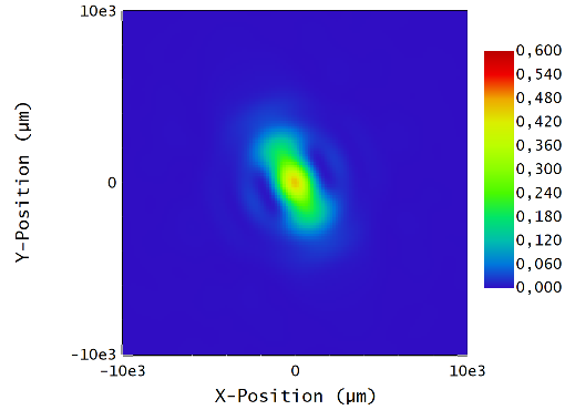
- You're right, 1 figure is more explicative that 100 words, in this case. The focus figure you sent answers most of the questions and gives a very clear diagnosis of the problem: the main dish (M1) is significantly astigmatic. To realise what "significantly" means for such an optical system, here is the focus sequence I obtain, when I distord M1 radius of curvature along 1 axis (so it becomes biconic) by a factor 6*10^-5 (which means that the curvature has changed such that the edge of M1 along this axis is less than 0.7 mm away from the optimal position) [yes a very very small fraction is sufficient!]:
These are Polychromatic Huygens PSF of the central field in the Nasmyth coordinates, for a point source at 38° elevation, with linear scale, and focus changes by 0.8 mm ; so very similar quantity to the one displayed in the maps of the focus sequence you sent; the M2 position in this series as defined in Zemax, are respectively: -0.7 mm, -1.5 mm, -2.3 mm


- As for the day/night variation, the above gives already a hint of answer.
I checked, that a contraction/dilatation of the M1 parabola by +/-5*10^-5 is sufficient to create a focus variation by +/- 1 mm. It doesn't require much imagination to convince oneself that qualitatively speaking temperature variations can create such contraction/dilatation of the parabola (...and that temperature inhomogeneities in its structure have dramatic consequences).
