Contents
PIMP - Pet(it) Interferometer Martin-Puplett
The PIMP is a compact Martin Puplett Interferometer (MPI) constructed in house by Institut Neel and IRAM. It was specifically designed to be able to perform measurements of the NIKA2 transmission directly at the telescope in complement to those performed at the lab with the Neel-LPSC MPI.
Documentation on wiki.iram.fr
Some documentation on PIMP is available in the NIKA2 private wiki documentation page. See
- Original specifications document containting some drawing giving an idea on how the frame is mounted on the HWP pedestal.
- Control computer documentation is the document written by Aurélien Bideaud explaining how to start and control the PIMP. It is already printed at the telescope, on the NIKA2 table in control room, and in the PIMP box. You can skipp the first part on the Raspberry and start ready from User Manual on page 5.
- Purpose and optics simulations is a presentations SL had prepared almost 6 years ago but never showed, because SL wanted to combine its presentation with presentation of the results from Juan. It explains very quickly the purpose of the PIMP in the main lines, and based on Zemax simulations explains the purpose of the convergent lens and the divergent lens you will find in the PIMP box.
- Video and photos showing the start of a PIMP scan and pictures with different orientation of the PIMP (once the PIMP is installed, use the crank handle on the side opposite to the cryostat to rotate it, and the pin break to maintain id at a given orientation)
Daily reports from previous installations
https://publicwiki.iram.es/Nika2DichroicChange (2018 observations)
https://publicwiki.iram.es/DailyReportsNika2Run33 (2019 observations)
https://publicwiki.iram.es/DailyReportsNika2Pool140125 (Test of functionality in the lab at the 30m)
Quick installation guideline with photos
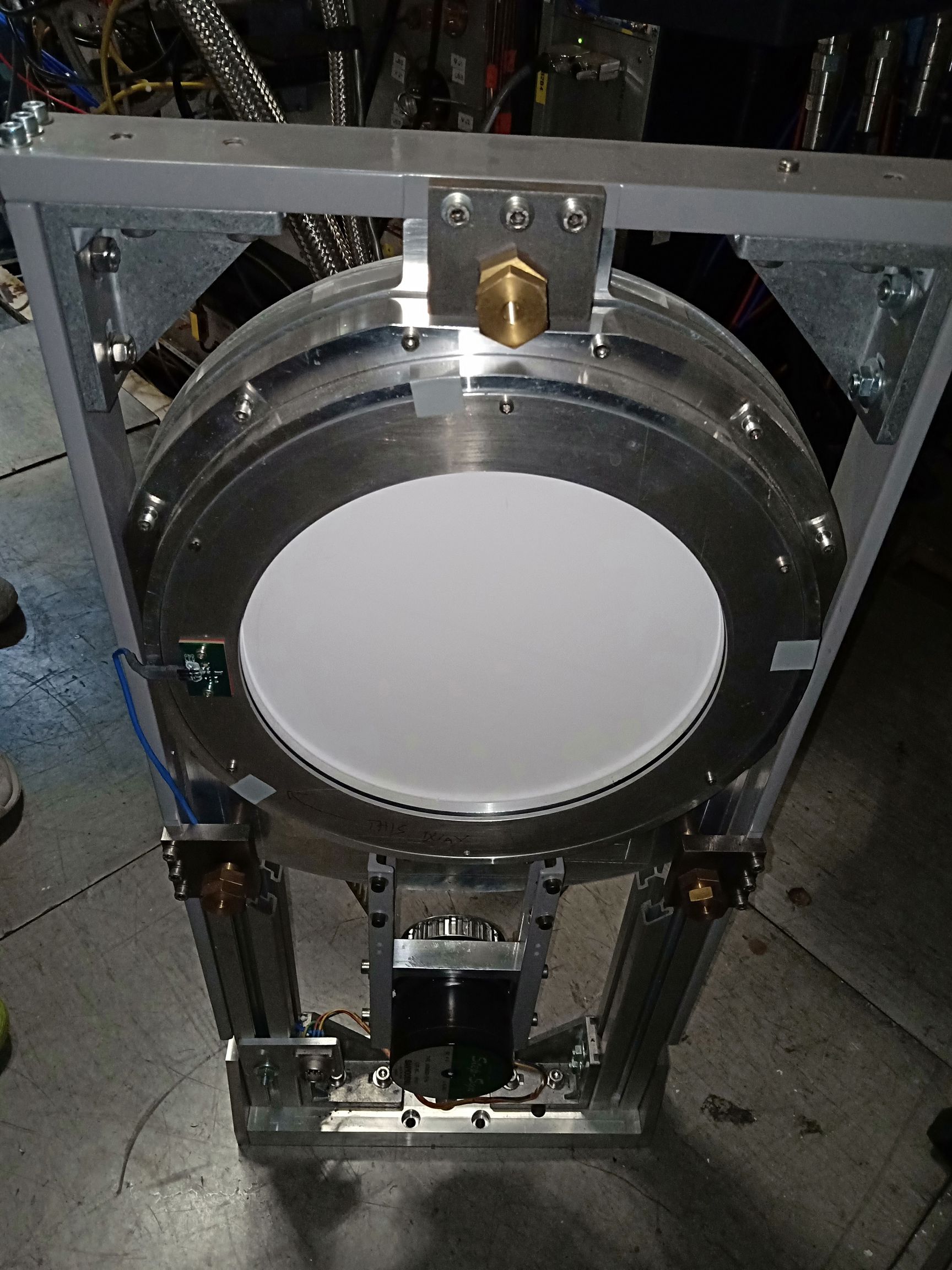
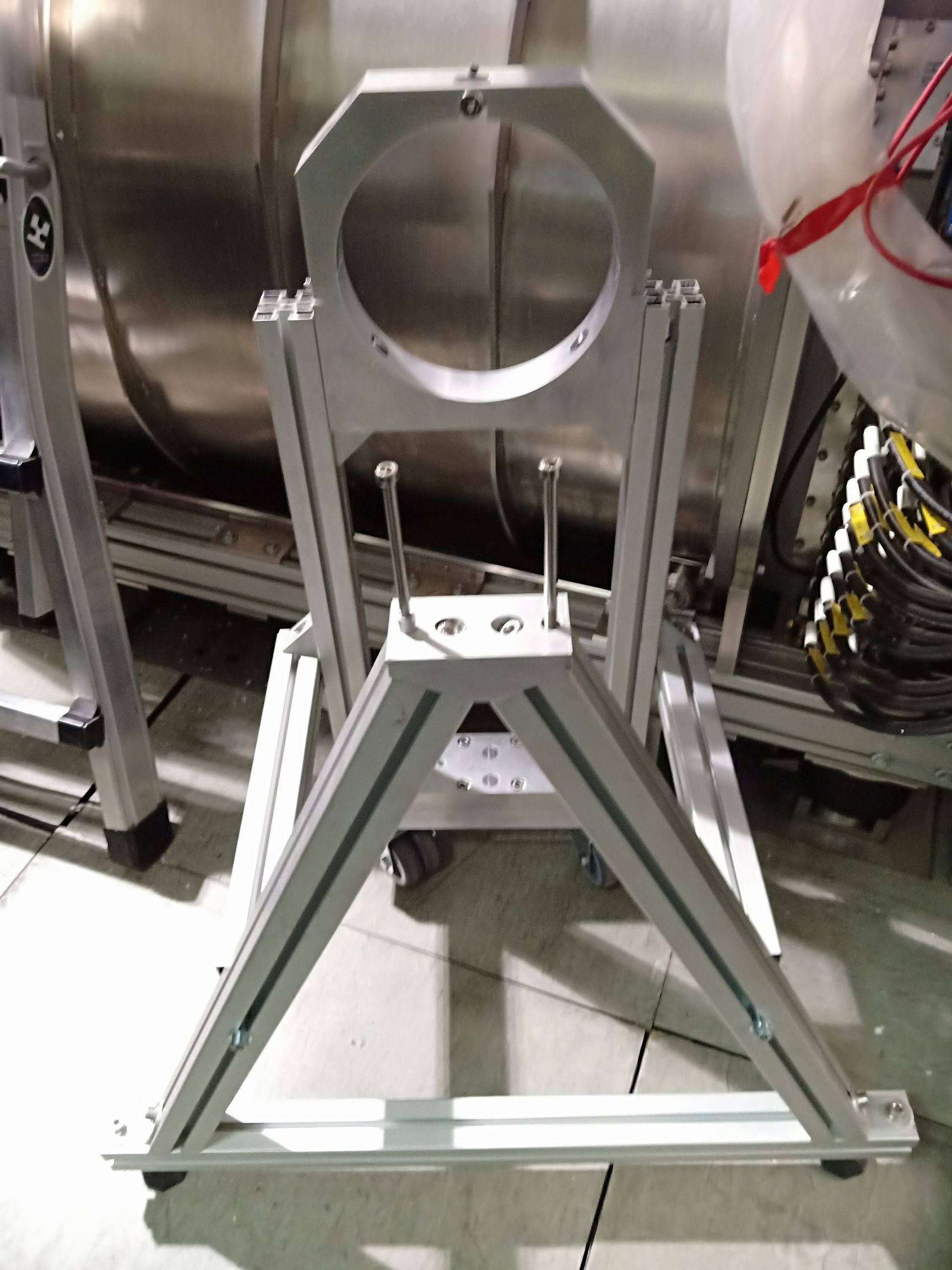
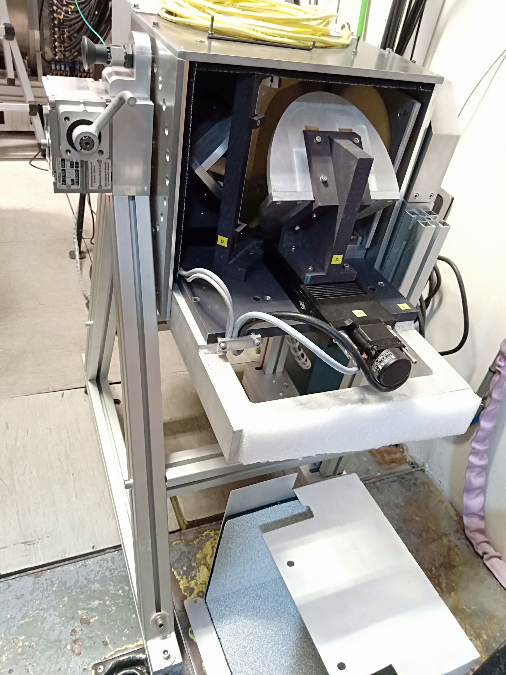
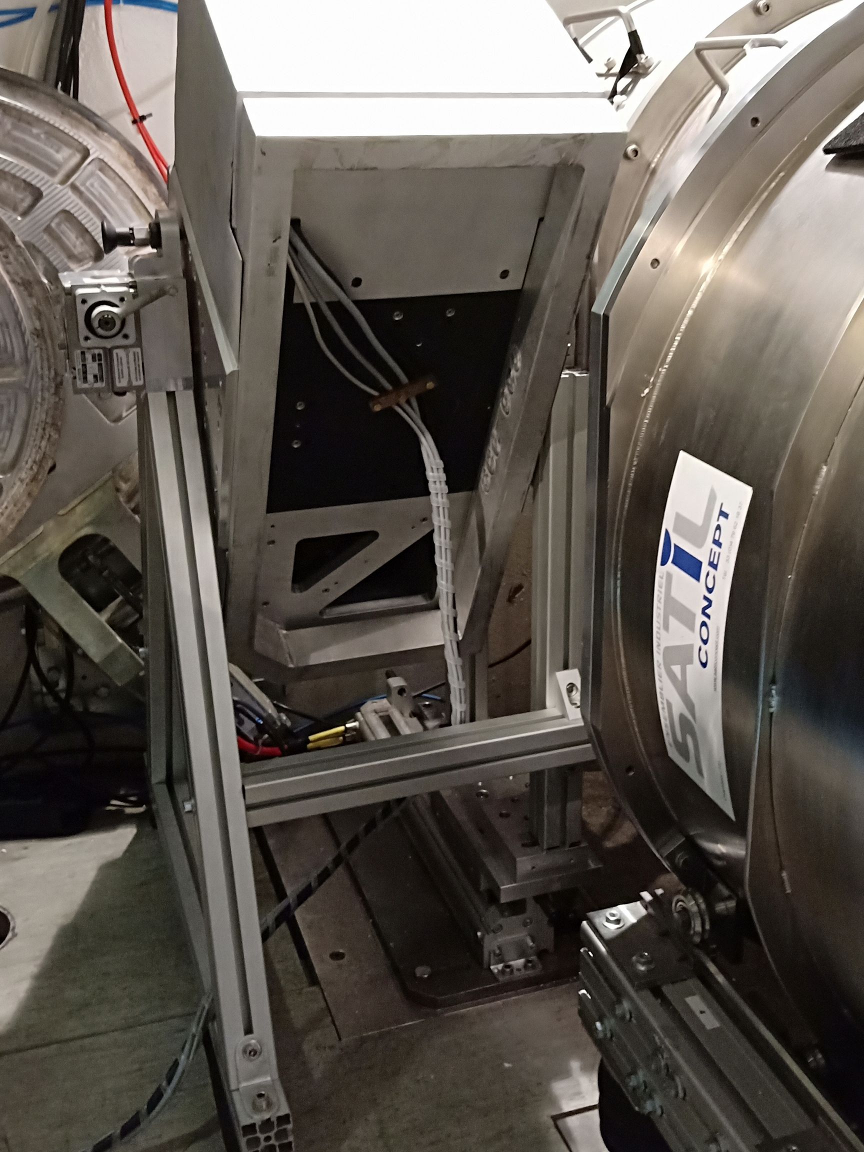
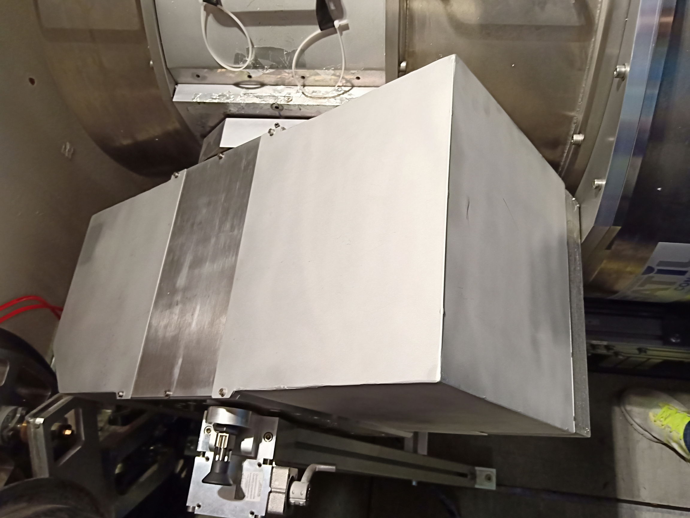
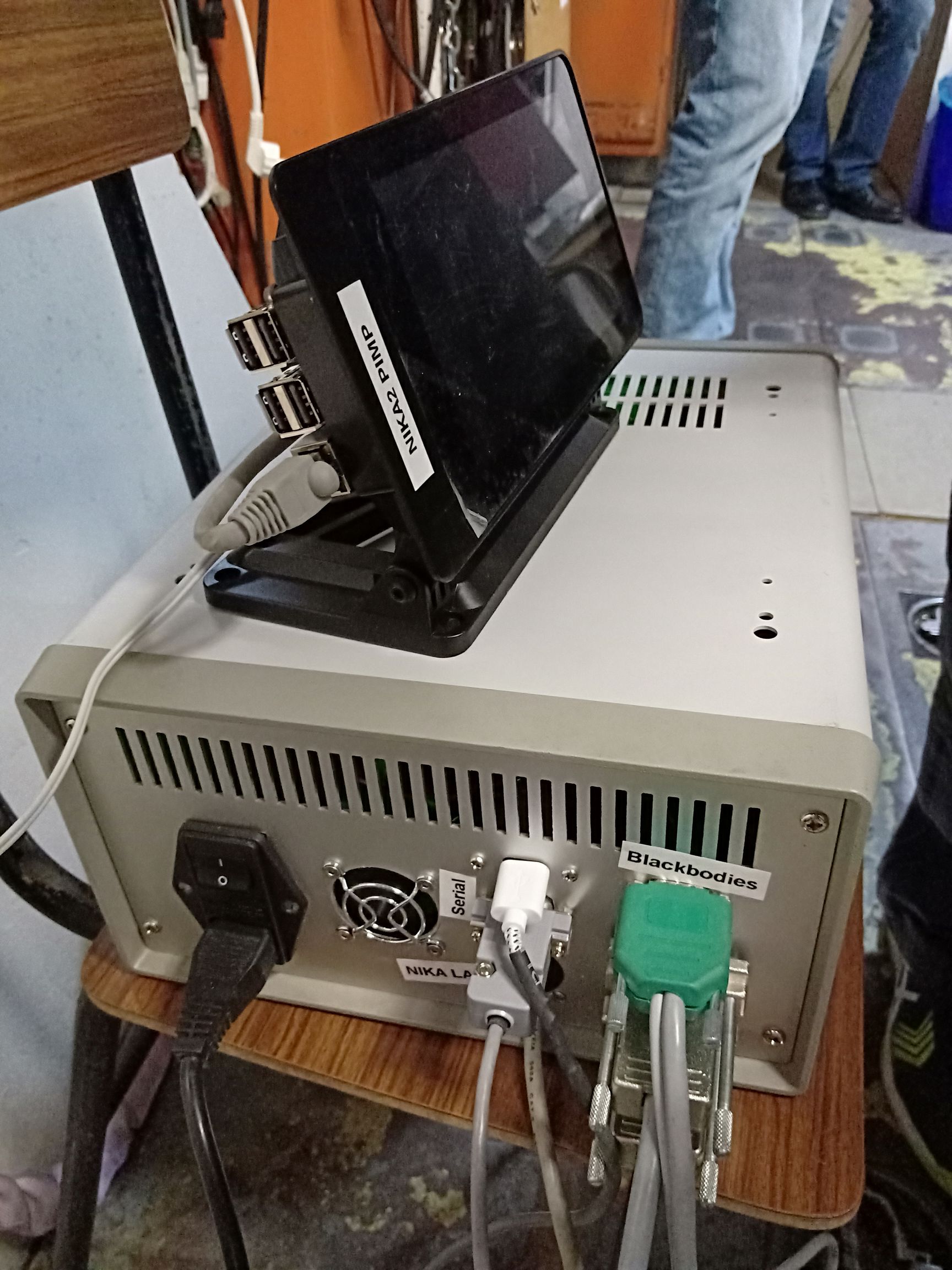
Below find 5 additional pictures that can help for the installation of PIMP. Some explanation for each of them:
- HWP dismounted: so you can see which part of the HWP assembly has to be dismounted from ist rail system.
- PIMP frame: just before putting the PIMP main element on it; to put the main element you have to unscrew and remove the top half of the hole where the output optics of the PIMP has to stand, then you install the PIMP main element and put back the piece that forms the top half of the hole. On the other side, unscrew the long rods fist, then put them back once the PIMP main element is in place.
- PIMP on its frame: to see how it looks when the 2 parts are assembled.
- PIMP installed for NIKA2: look in particular at the feet of the frame, how it is screwed to the piece that lies on the HWP rail system.
- PIMP NIKA2 minimal spacing: when its correctly installed, see how close is the PIMP output to the NIKA2 window, and the minimal spacing between PIMP frame and the NIKA2 piece making the interface between the cryostat nose and main body, when we rotate the PIMP.
- PIMP electronics: Raspberry control unit and gray box Electronics plugged.
How to setup the PIMP with the acquisition
when the pimp is plugged on the NIKA2 network, it sends various kind of data to the network (scan start and stop, the speed, frequency and so on). These data can be read by the NIKA2 acquisition, providing that there's the correct variable declarations in the ini file. The Pimp is treated by the acquisition like an "instrument", exactly like each Nikel board is treated. If you look in the folder where the ini file are you will find 3 ini files that contain PIMP specific variable declarations. You will have to use them. If you are not so sure about these ini file you can have help from Juan, Martino, and Alessandro.
Measurements of the NIKA2 bandpasses
- 2018, 2019 campaigns:
Two campaigns were performed in summer 2018 and 2019. Different angles of the PIMP polarizer with respect to the NIKA2 polarization reference frame were explored. Overall it was found that the NIKA2 bandpasses reconstructed with the PIMP are fully consistent with those measured previously in the lab at Neel. As of Jan-2025 and in preparation of the NIKA2 upgrade in March 2025, a report has been drafted by J.Macias-Perez, A.Bideau, S.Leclercq, A.Monfardini.
The measurements in 2019 were done as follows (taken from the daily report): Cold black body at 30°, hot black body at 110°. Need to set PIMP control at 19200 bauds in order to get the interferograms (I or Q vs position) in the acquisition software trace screen. WE set Fmax to 892 GHz and the resolution to 5 GHz. Two series of measurements were done: 7 scans per series, 10 subscans per scan. Series 1 was done with the convergent lens at the output of the PIMP, series 2 was done with the divergent lens at the output of the PIMP ; each of the 7 scans per series is done at a different tilt angle of the PIMP: 270°, 300°, 330°, 0°, 30°, 60°, 90°.
- March 2025 campaign:
- run84_pimp.ini file checked against DAQ: looks okay
- Scans list (at ~/NIKA/Data/run84_X/X36_2025_03_21/ folder):
Filename
Tilt angle
Optics
16:23:47
0
Divergent
16:26:16
0
idem
idem
Created: 2025.Mar.20 created by CK from e-mails of SL.

