|
Size: 3664
Comment:
|
Size: 3648
Comment:
|
| Deletions are marked like this. | Additions are marked like this. |
| Line 18: | Line 18: |
| * In between, there is a large near-side lobe, especially at 2mm (but also visible at 1mm), that shows up as a rectangular pyramid-like shape at the 10% level, the origin of which is unknown. It seems to scale with wavelength. It was not so apparent in NIKA. Therefore the quality of the dichroic is not at the center of this issue. ''In fact the rectangular shape of the first side lobe is known (but I recognize I didn't communicate about it until now) and expected from optical simulations; see the figure at the bottom of this page. It is due to the combined diffraction on the primary mirror and the tetrapod holding the secondary mirror. -SL-'' | * In between, there is a large near-side lobe, especially at 2mm (but also visible at 1mm), that shows up as a rectangular pyramid-like shape at the 10% level, the origin of which is unknown. It seems to scale with wavelength. It was not so apparent in NIKA. Therefore the quality of the dichroic is not at the center of this issue. ** __In fact the rectangular shape of the first side lobe is known (I recognize I didn't communicate about it until now) and expected from optical simulations. It is due to the combined diffraction on the primary mirror and the tetrapod holding the secondary mirror. However, the expected level of this side lobe is ~2% of the central peak when the focus is correct, and this level increase to 10% if the defocus along the Z axis of M2 is ~0.7 mm. See the figure at the bottom of this page for more details. -SL-'' |
| Line 36: | Line 37: |
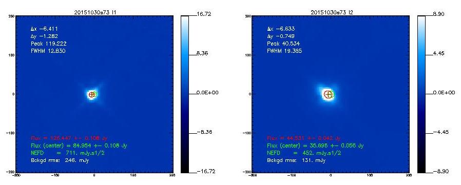
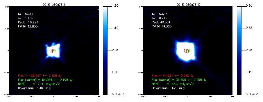
| {{attachment:Beam_Mars_20151030s73b.jpg||height=500}}{{attachment:Beam_Mars_20151030s73b_foot.jpg||height=500}} | {{attachment:Beam_Mars_20151030s73b.jpg}}{{attachment:Beam_Mars_20151030s73b_foot.jpg}} |
| Line 38: | Line 39: |
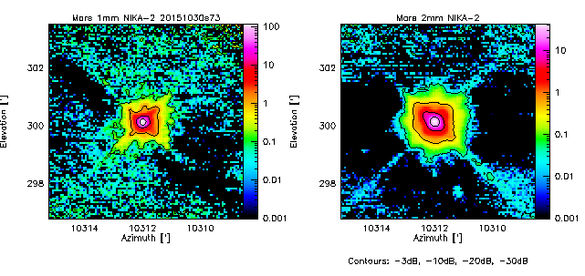
| {{attachment:beam20151030s73.png||height=650}} | {{attachment:beam20151030s73.png}} |
| Line 42: | Line 43: |
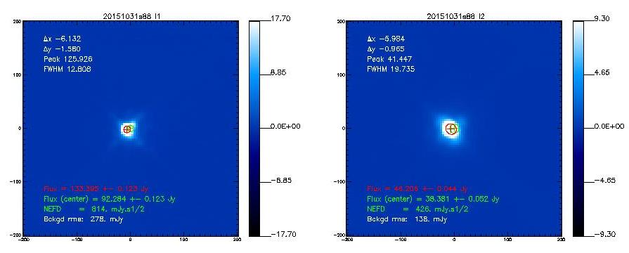
| {{attachment:Beam_Mars_20151031s88b.jpg||height=500}}{{attachment:Beam_Mars_20151031s88b_foot.jpg||height=500}} | {{attachment:Beam_Mars_20151031s88b.jpg}}{{attachment:Beam_Mars_20151031s88b_foot.jpg}} |
| Line 44: | Line 45: |
| {{attachment:beam20151031s88.png||height=650}} | {{attachment:beam20151031s88.png}} |
| Line 48: | Line 49: |
| {{attachment:Beam_Mars_20151028s103b.jpg||height=500}}{{attachment:Beam_Mars_20151028s103b_foot.jpg||height=500}} {{attachment:beam20151028s103.png||height=650}} |
{{attachment:Beam_Mars_20151028s103b.jpg}}{{attachment:Beam_Mars_20151028s103b_foot.jpg}} {{attachment:beam20151028s103.png}} |
| Line 55: | Line 56: |
| {{attachment:Beam_Uranus_20151029s217b.jpg||height=500}}{{attachment:Beam_Uranus_20151029s217b_foot.jpg||height=500}} | {{attachment:Beam_Uranus_20151029s217b.jpg}}{{attachment:Beam_Uranus_20151029s217b_foot.jpg}} |
| Line 57: | Line 58: |
| {{attachment:beam20151029s217.png||height=650}} | {{attachment:beam20151029s217.png}} |
| Line 61: | Line 62: |
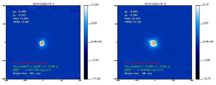
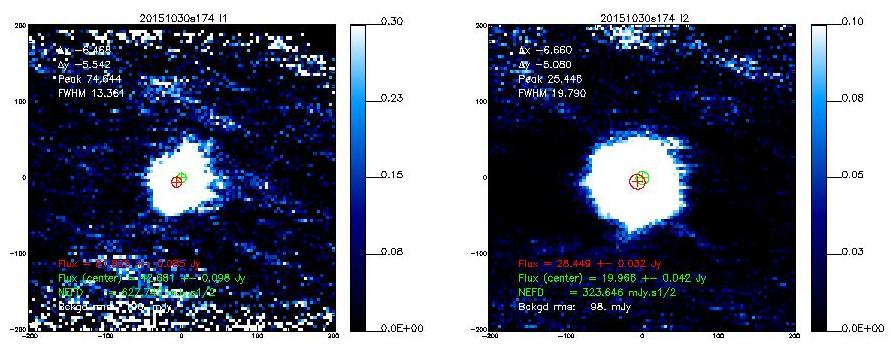
| {{attachment:Beam_Uranus_20151030s174b.jpg||height=500}}{{attachment:Beam_Uranus_20151030s174b_foot.jpg||height=500}} | {{attachment:Beam_Uranus_20151030s174b.jpg}}{{attachment:Beam_Uranus_20151030s174b_foot.jpg}} |
| Line 63: | Line 64: |
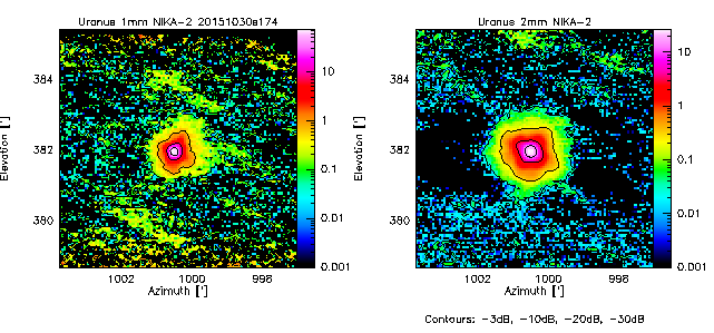
| {{attachment:beam20151030s174.png||height=650}} | {{attachment:beam20151030s174.png}} |
| Line 69: | Line 70: |
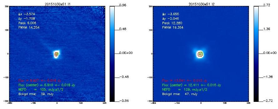
| {{attachment:Beam_3C84_20151030s51b.jpg||height=500}}{{attachment:Beam_3C84_20151030s51b_foot.jpg||height=500}} | {{attachment:Beam_3C84_20151030s51b.jpg}}{{attachment:Beam_3C84_20151030s51b_foot.jpg}} |
| Line 71: | Line 72: |
| {{attachment:beam20151030s51.png||height=650}} | {{attachment:beam20151030s51.png}} |
Describe OffProcNika2Run1Beam here.
Discussion on beams
Page last updated, FXD, CK, SL 2015-11-02 Figures OK
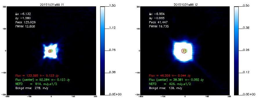
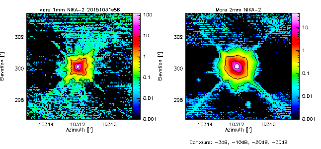
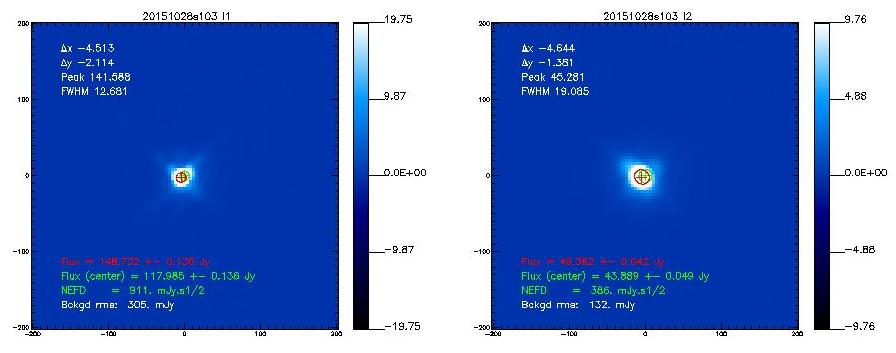
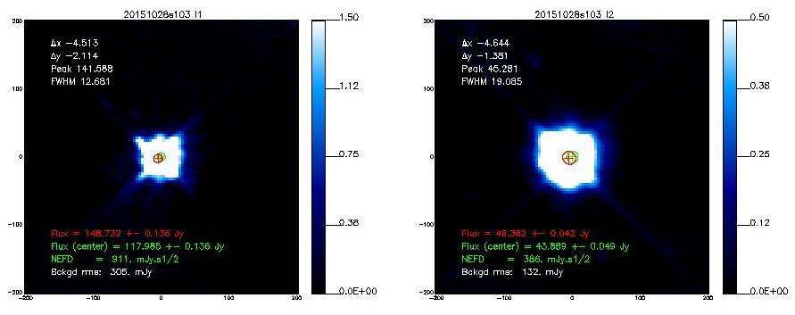
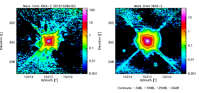
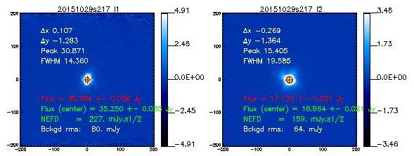
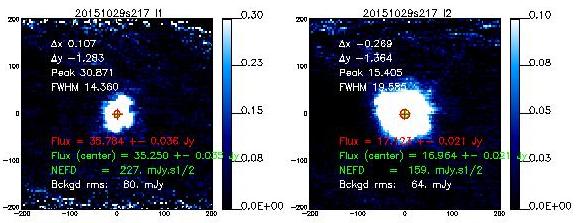
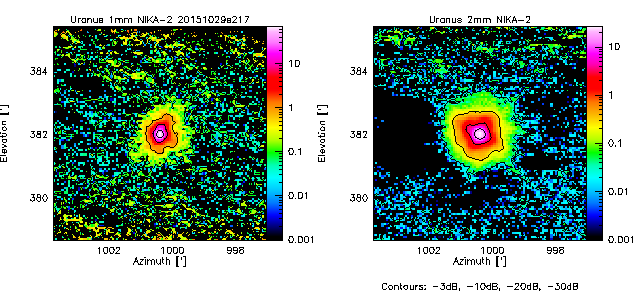
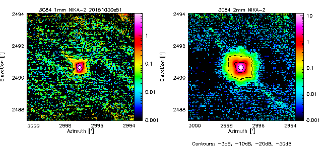
We measure the beam by using the middle scan of the 3-scans sequence launched with @beammap Here are the best-of on 3 sources.
Preliminary findings
- The main beam (the Gaussian part) seems with a normal width aka 11", 17" (but only in single-pixel analysis). Blind 2D Gaussian fits to the maps result in broader beams of 13", 19.5" (see Table below).
- The quadrupod holding the secondary gives clear diffraction marks as a faint cross at about -30dB, visible in all Mars scans. Uranus and 3C83 are not bright enough to reach -30dB. To go deeper, we need Saturn or Jupiter maps.
- In between, there is a large near-side lobe, especially at 2mm (but also visible at 1mm), that shows up as a rectangular pyramid-like shape at the 10% level, the origin of which is unknown. It seems to scale with wavelength. It was not so apparent in NIKA. Therefore the quality of the dichroic is not at the center of this issue.
* In fact the rectangular shape of the first side lobe is known (I recognize I didn't communicate about it until now) and expected from optical simulations. It is due to the combined diffraction on the primary mirror and the tetrapod holding the secondary mirror. However, the expected level of this side lobe is ~2% of the central peak when the focus is correct, and this level increase to 10% if the defocus along the Z axis of M2 is ~0.7 mm. See the figure at the bottom of this page for more details. -SL-
For comparison, see the NIKA-1 beam maps in Fig.8 of Catalano+2014 and in Fig.8 of Monfardini+2011.
- The following table shows the FWHMs derived from 2D-Gaussian fits to the observed emission.[Note that if the error beam is included in the fit, the main beam narrows down]
Source
Date/Scan
HPBW
HPBW
1mm
2mm
Mars
20151030s73
12.9
19.3
Mars
20151031s88
12.7
19.6
Uranus
20151029s217
14.5
19.5
Uranus
20151030s174
13.2
19.7
3C84
20151030s51
14.3
19.4
Beams on Mars
- 20151030s73
- 20151031s88
- 20151028s103
Beams on Uranus
- 20151029s217
- 20151030s174
Beams on 3C84
Theoretical beams from Zemax simulations (for comparison)
The image shows the beam at 1mm. For the 2mm band the shape is strictly identical, it is just twice bigger. (SL 2015-11-02)

