Discussion on NIKA-2 beams
Page created by FXD, CK
Last updated by CK 2016-02-02, SL 2015-11-02, JFL 2015-11-07, NB 2015-11-11
Contents
-
Discussion on NIKA-2 beams
- Astigmatism
- Comparison of NIKA2 beam with NIKA1, GISMO, EMIR (CK, 02-Feb-2016)
- Primordial problem: synchronization (RZ, 2016-01-11)
- More on NIKA2 beams change across the FoV (JFMP, 2016-01-03)
- NIKA2 beams change strongly across the FoV (RZ, 2015-12-03)
- Beam maps on Mars
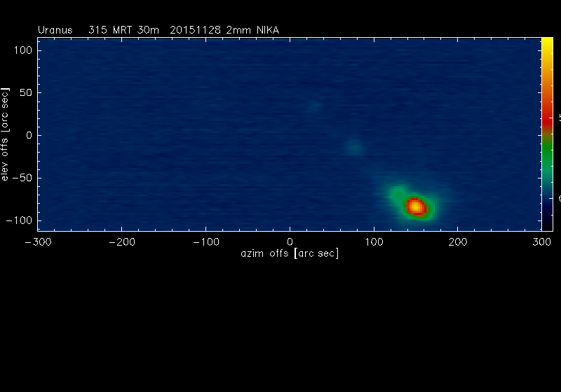
- Beam maps on Uranus
- Maps on 3C84
- Series of small maps on 3C84 by JFL under poor conditions
- Preliminary findings
- Maps seem too small ! Comment by RZ
- Theoretical beams from Zemax simulations (for comparison, SL 2015-11-02 and 04)
- Beam Profiles (NB)
- Fits for Beam Maps, radial profiles, integrals, NIKA2-EMIR (October-2015, FXD-NP, CK)
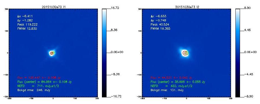
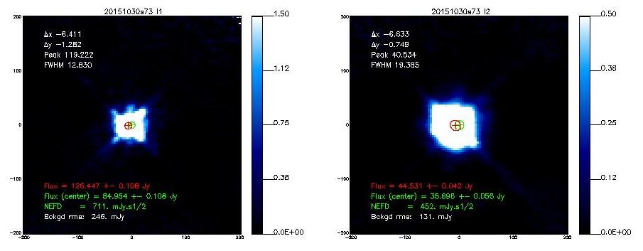
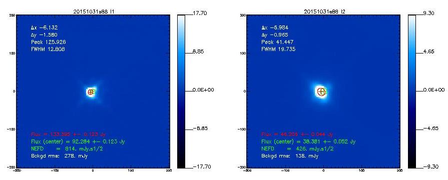
If not said otherwise, we measure the beam by using the middle scan of the 3-scans sequence launched with @beammap . These are 20'x20' maps done on-the-fly with 55"/sec scanning speed. Here, we show the best-of on 3 sources.
Astigmatism
JP is constantly monitoring the temperature structure of the telescope via many sensors placed at different parts of the antenna. This allows him to predict the amplitude of astigmatism. Attached is a plot showing this predicted amplitude and its variation during last month February. There is a good correlation with the temperature difference between the backstructure and the reference sensors placed in the top part of the yoke. Notice also the often marked day/night variation.
If we suspect that the 10% shoulder seen in the beam profiles of NIKA2 stem from astigmatism, we should often notice a diurnal variation. That is something to be checked.
resumeAstigm-Feb2016.pdf Predicted astigmatism amplitude of the primary mirror from temperature sensor values for February 2016 by JP.
Comparison of NIKA2 beam with NIKA1, GISMO, EMIR (CK, 02-Feb-2016)
NIKA1 and NIKA2
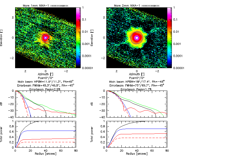
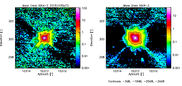
NIKA1 maps at 1mm and at 2mm (Map _0_ of JMP 26-Jan). Radial profiles: In black are shown the NIKA1 profiles. The green line corresponds to the radial average of the NIKA2 map (right). In red shown are radial profiles at 145 and 250GHz, which are deduced from lunar scans with EMIR and include the main beam, three modelled error beams, plus diffraction sidelobes (cf. errorbeam report 2013). After fitting a 2D-Gaussian to the main beam, it is subtracted. Another 2D-Gaussian is fitted to the residual map, to derive the properties of the errorbeam: Peak flux density and widths. Artefacts: The present figure still contains some artefacts: NIKA1 maps are slightly rotated.
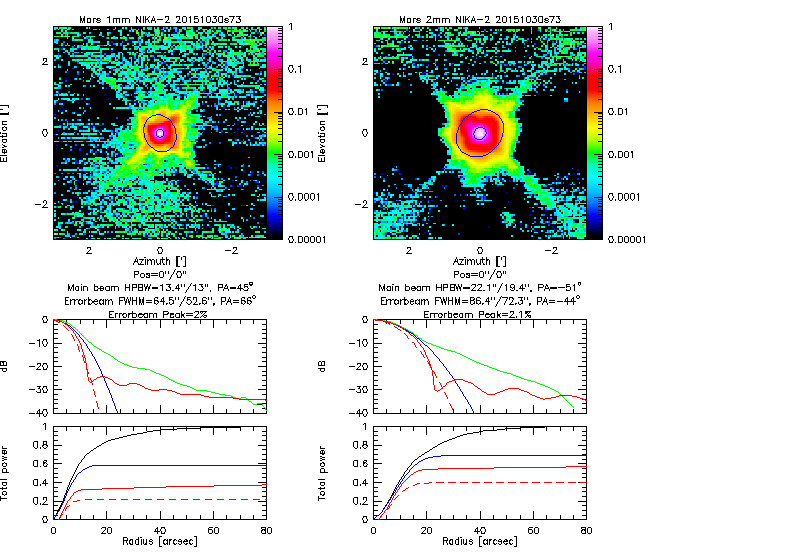
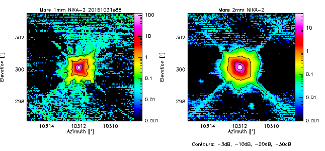
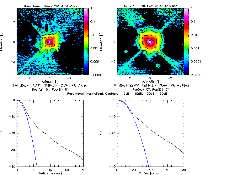
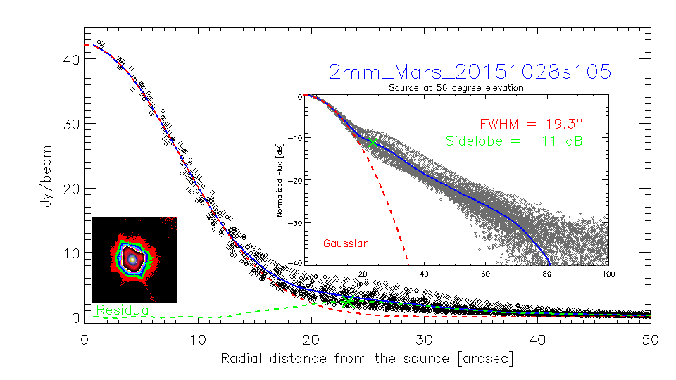
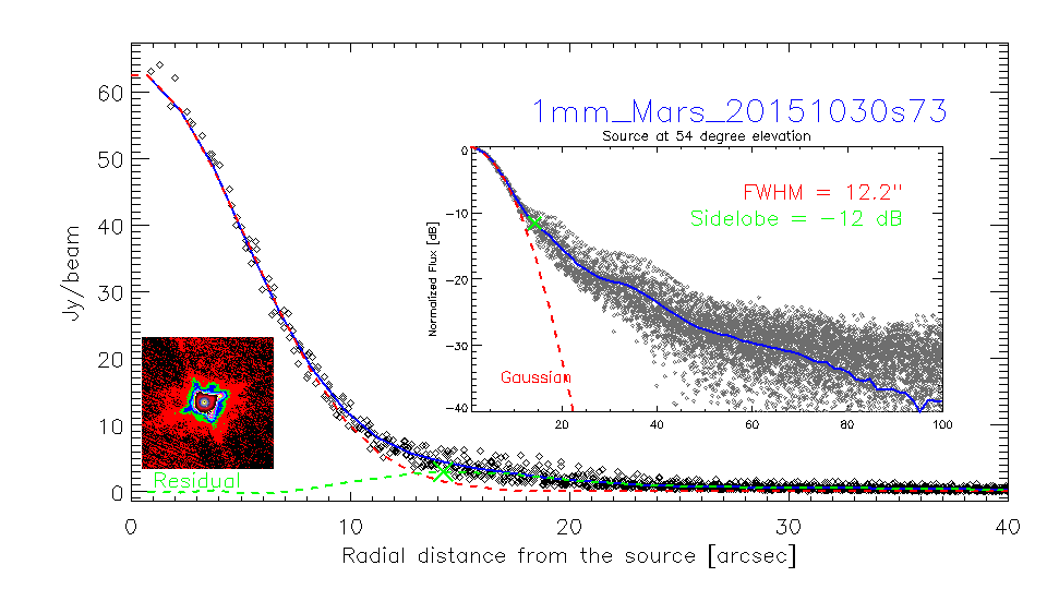
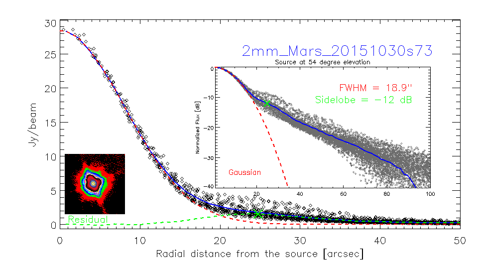
- NIKA2 maps on Mars taken on 30-Oct-2015 (Scan 73, UT=8).
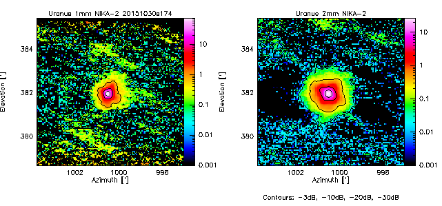
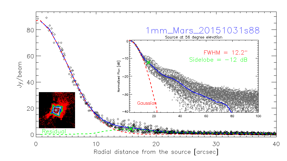
The radial profiles of NIKA1 and NIKA2 show a shoulder at -10dB and look almost identical down to the -30dB level. Maps show contours at -3dB, -10dB, -20dB, -30dB. The NIKA1 contour maps at -20 and -30dB look similar to the NIKA2 maps. In the NIKA2 2mm map, the encircled power relative to the main beam at 60arcsec radial distance is 31%; Catalano et al. (2014, Table 2) give 30% for NIKA1. In the NIKA2 1mm map, the encircled power relative to the main beam at 60arcsec radial distance is 41%, the same value given by Catalano et al. for NIKA1.
GISMO 2mm
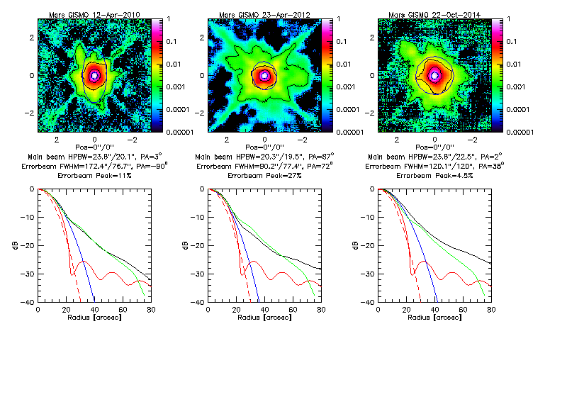
- Typical GISMO beam maps on Mars observed in 2010, 2012, and 2014: Contour levels are -3dB, -10dB, -20dB, -30dB. Radial profiles of GISMO (black), GISMO fitted Gaussian main beam (blue), NIKA2 (green, from Mars map of 30-Oct-2015), EMIR best fitting model (red, drawn), EMIR best fitting main beam (red dashed). Note that Mars is not pointlike.
- The 1st errorbeam was fitted with a Gaussian, after subtracting the fitted Gaussian main beam, keeping the 0/0 position fixed.
- Radial profiles compare pretty well with those of NIKA1/2 (at 2mm) with regard to the shoulder and errorbeam between -10dB and -20dB. For the GISMO profiles the -30dB level is a bit higher, but this may be due to a different retrieval of extended structures.
GISMO maps were taken from the crush homepage of A.Kovacs.
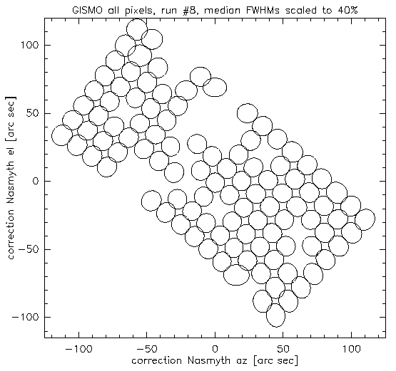
When comparing with the GISMO averaged beam it must not be forgotten that GISMO had quite strong distortion of the FoV and the individual beams varied significantly. The FoV of GISMO is shown below. (RZ, 2016-01-29) Isn't the distortion of the FoV taken into account in the data reduction ? (CK) Positions of the beams yes, but you cannot "account" for the distortion of shape of the main & error beams (depending also on elev ?). (RZ)
Conclusions
- Optical simulations by SL (see below) indicate that an error beam of roughly the observed shape is caused by how the KIDs illuminate the primary. We still need to compare qualitatively the observed size with the simulation.
- The important question is why the 1st error beam which has been seen with all continuum cameras (GISMO, NIKA1, NIKA2) is so strong, and not varying in strength it seems.
- The source of this errorbeam must be from parts of the system which were shared by NIKA1, NIKA2, and even by GISMO. This points at the primary and secondary, but also possibly at the way the detectors illuminate the primary. As the averaged beam pattern is unchanged after a big change in the optics, the new NIKA2 optics (external and internal to the cryostat) can hardly be the culprit for the strong errorbeam.
- Of course it is important, to discuss beam shapes of individual areas in the FoV, or even of individual KIDs. It would be very interesting to focus on the central pixel and check the resulting beam map of the central pixel. This compares best to the situation with EMIR's one focussed pixel.
- Possible explanations of the strong error beam:
We might have the suspicion that the 30m antenna often shows large scale deformations leading to the strong errorbeam we see easily with NIKA2 and NIKA1. If so, we should see a clear variation with UT, between beam maps taken at daylight hours when the sun is illuminating and distorting the dish, and late night hours under stable clear sky conditions. To check at any time, we could combine NIKA2 beammaps with quick EMIR observations of the beam efficiencies. EMIR day-time observations should show a degradation of beam efficiencies corresponding to the strong errorbeam seen in the NIKA maps. If this suspicion is correct, NIKA2 beammaps taken in the 2nd half of the night before sunrise, should show a significantly reduced first errorbeam. Right now, Mars is visible early in the morning hours after 5:30am above 30deg, well before sun rise.
One possible explanation is that all the above NIKA2, NIKA1, and GISMO maps were de-focussed. Simulations show that an axial defocus by only 0.7mm leads to an increase of the errorbeam level to -10dB (see explanations by SL below). To investigate, NIKA2 beam maps were taken with different foci in January 2016.
Primordial problem: synchronization (RZ, 2016-01-11)
The synchronization problems btw the receiver and the telescope show up in the standard maps az a zig-zag of the source position from one row to the next. The time difference with respect to the master telescope clock is given by deltaT = 0.5*zigZag/scanningVel
In the example shown below the zigZag in the scanning direction is ~3.5arcsec for scanningVel ~55arcsec/sec. This gives deltaT~30msec btw A_t_utc and the master telescope clock. (I chose as example an out-of-focus map because due to the astigmatism the Main Beam becomes elliptical, with the minor axis even smaller than the nominal value and the increased major axis allows to compare more rows on source, when the elongation is perpendicular to the scanning direction.)
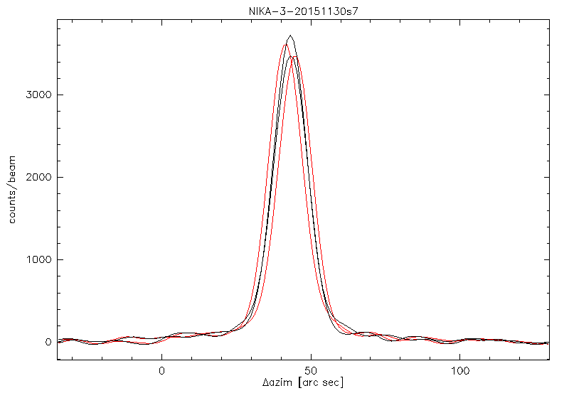
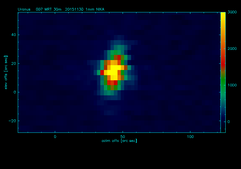
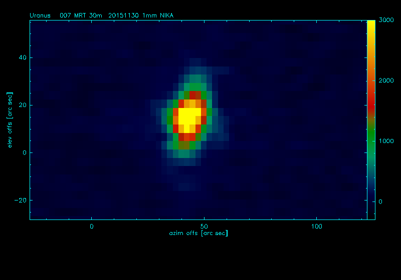
left: in red - the source distribution in two adjacent rows using A_t_utc, in black - using A_t_utc+30msec; centre: beam without, right: with A_t_utc correction. As in this map all usable beams show identical zigZag anomalous refraction as a reason for this zigZag can be ruled out.
However, as the time difference btw the two NIKA2 clocks shows a considerable variation the time difference btw NIKA2 A_t_utc clock and the master telescope clock is most probably not constant. This is very hard to demonstrate using on-sky data as the atmosphere limits the determination of deltaT from the zigZags to ~5-10msec at best (depending on scanning_vel).
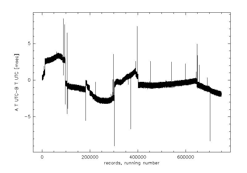
above: A_t_utc - B_t_utc for 52 scans
For completeness another synchro-problem has to be mentioned, though it does not really affect the calculation of the Main Beam size: the synchronization between the commanded action of the telescope (subscan structure) and the NIKA2 data acquisition. The switch on and off of NIKA2 does not correspond to the subscan starts/ends. The time difference might be even 1min ! Observations which require tuning per subscan (e.g. skydips) were therefore completely desynchronized.
Last not least: the described synchro-problems are not new, i.e. special for NIKA2; they are documented since the first run with NIKA.
More on NIKA2 beams change across the FoV (JFMP, 2016-01-03)
As discussed below by RZ we observe large variations on the shape of the NIKA2 beams across the FOV. RZ on one hand and BC on the other and have shown with independent analysis that the NIKA2 beams get wider and more distorted as we move away from the center of the FOV, while homogeneous beam shapes are expected from optics design (SL). To check this in more details we have checked the geometry beam maps KID per KID and identify the following catétories: not distorted, distorted beams, double KIDs, very close double KIDs, and identical KIDs:
The distribution of those categories across the FOV are represented in the figures below.
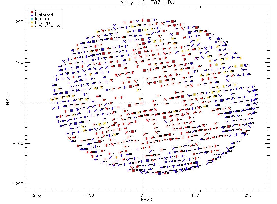
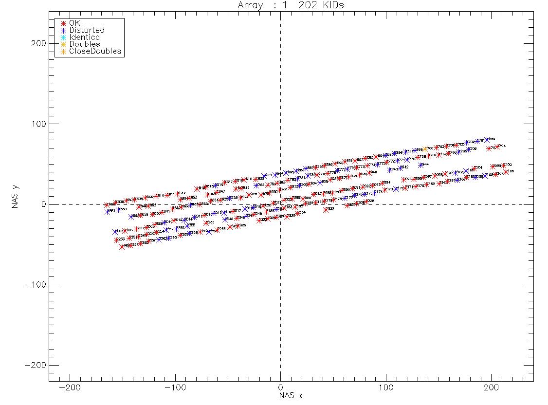
We observe that as identified by RZ, BC and SL, most of the distorted beams are in the edges of the FOV, however this is not the case for all. We observe a relatively important number of double or very close double (distorted beams showing two main beam like features). Finally we have identfied two couples of identical KIDs (exactly same properties).
Given the observed of the NIKA2 beams we need most probably to perform the caracterisation of the NIKA2 beams per KID. This might be one of the priorities of next observation campaign. We probably need to combine various beammap scans and/or improve the observation step.
NIKA2 beams change strongly across the FoV (RZ, 2015-12-03)
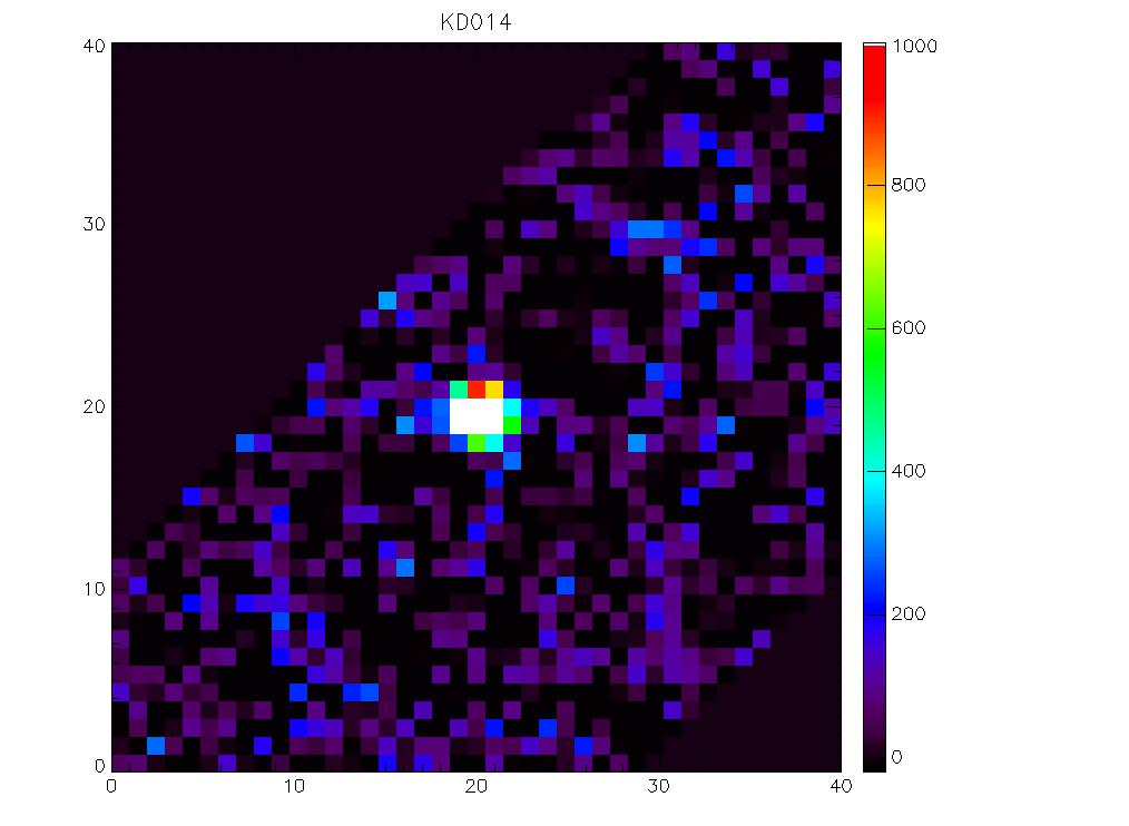
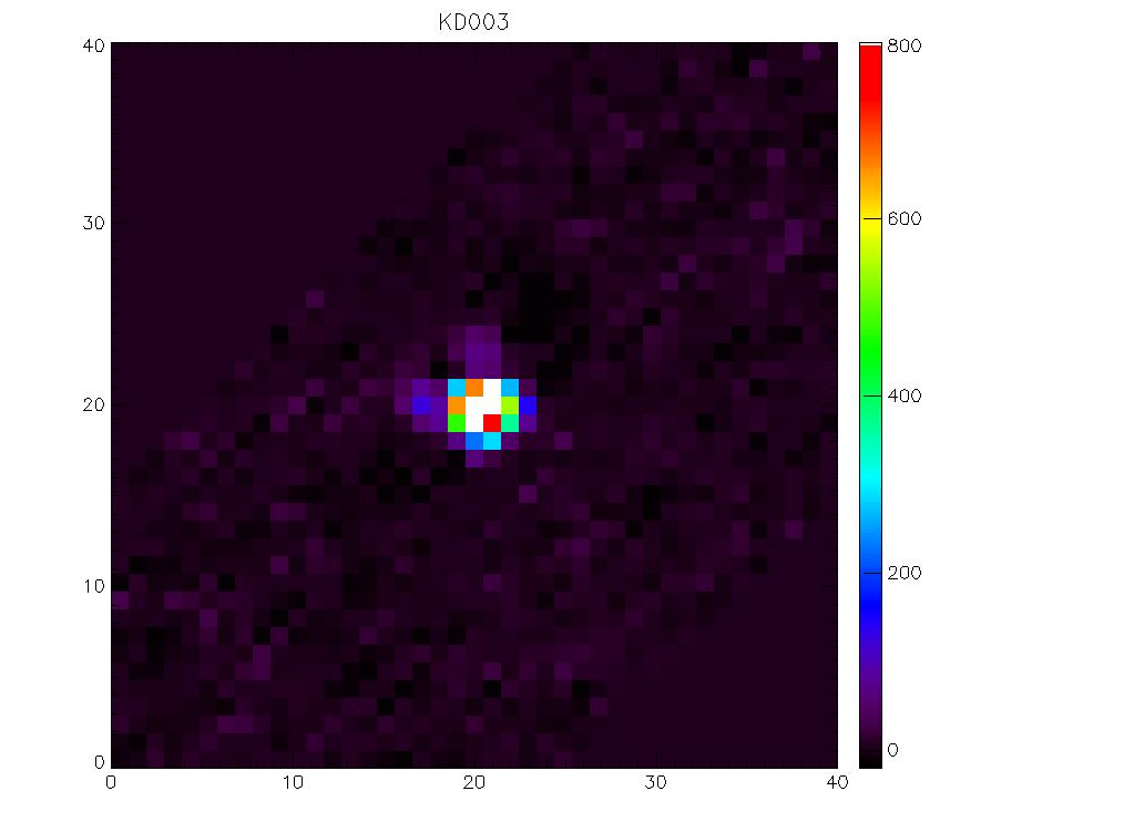
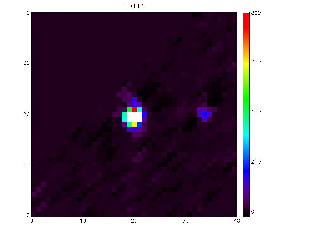
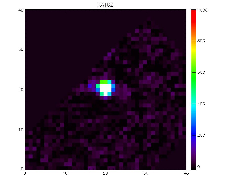
The NIKA2 beams become very elliptical to the edges of the arrays, even with a ghost secondary beam @2mm (can hardly call it a side lobe). Therefore the analysis of the average beam cannot help much to understand the physics behind.
Further problem is the stability of the data. All 3 arrays show large (i.e. at a couple of Jy level) different kind instabilities, with even >50% of pixels affected. This strongly affects the concerned beams, thus also the average.
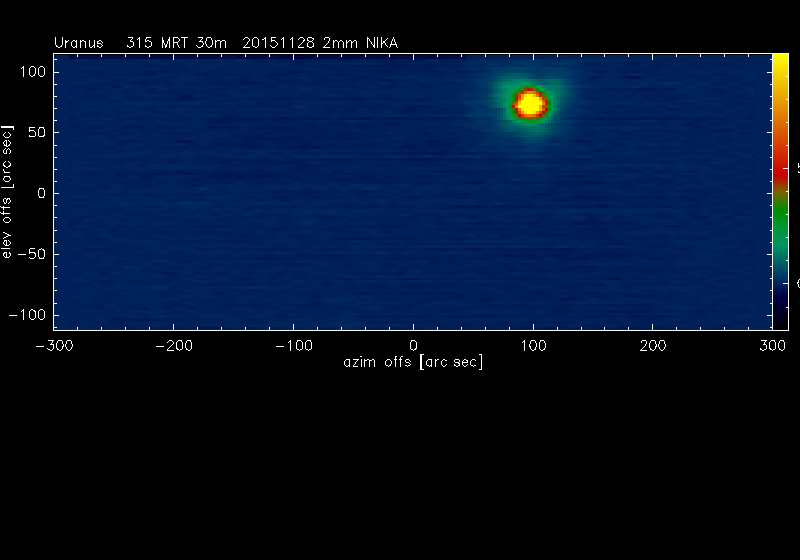
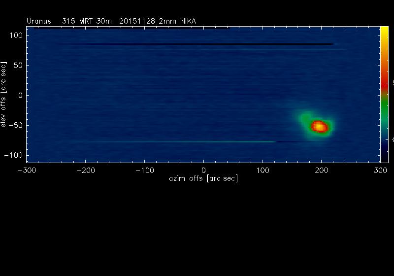
Examples of 2mm beams in the central region and at the edge of the array. For the 1mm beams see DailyReportsNika2Run2, Nov 26.
Beam maps on Mars
- 20151030s73
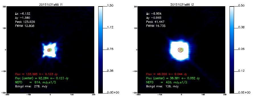
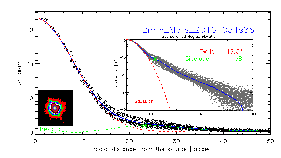
- 20151031s88
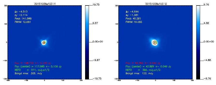
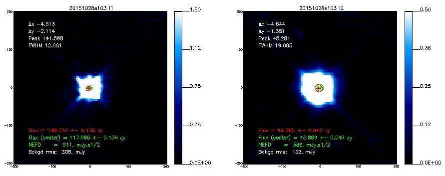
- 20151028s103
Beam maps on Uranus
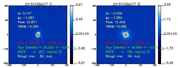
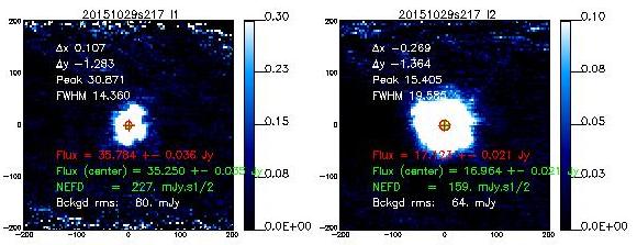
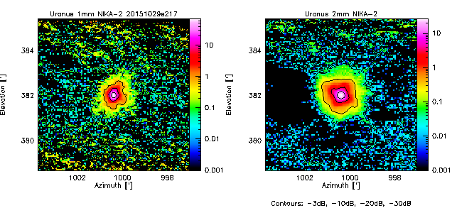
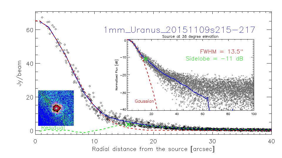
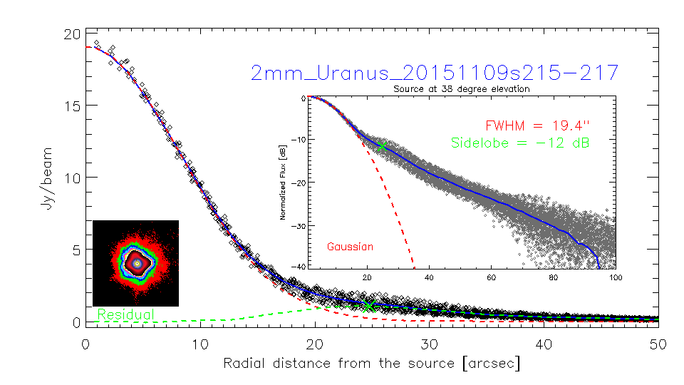
- 20151029s217
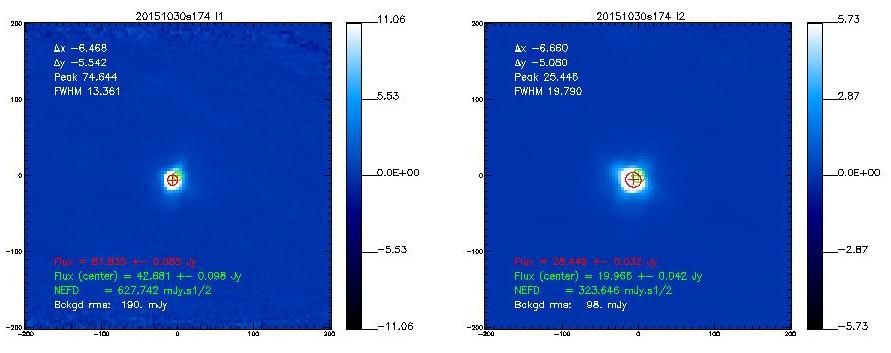
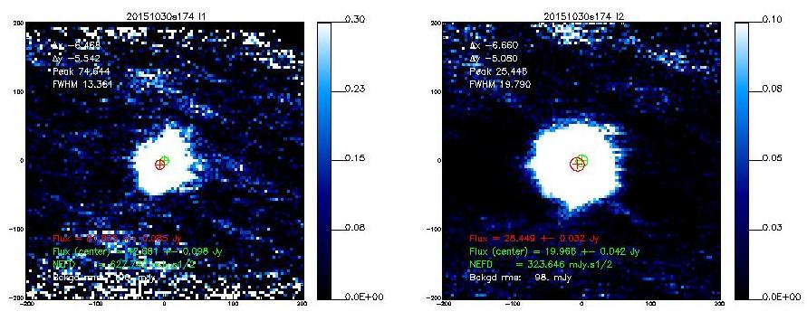
- 20151030s174
Maps on 3C84
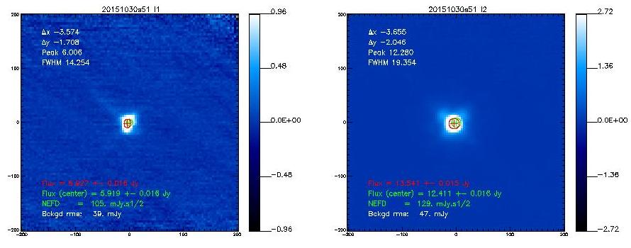
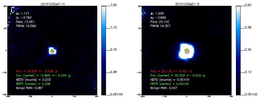
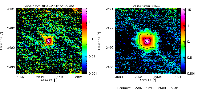
- 20151030s51
Series of small maps on 3C84 by JFL under poor conditions
- A short report on NIKA2 beamwidth using repeated observations of 3C84 at elevations between 52 and 73 deg in poor weather condition (tau_225 ~ 0.7).
Means and rms with 30 SMALL (5'x5' : nkotf 5 5 0/90/135/45 0 30 60 AZEL) on 3C84 (scans 20151104s21, s22, s23, scans 20151105s13, s14, s15, s16, s17, s19,
scans 20151106s15, 18, 22, 23, 24, 25, 26, 27, 28, 29, 30, 32, 33, 34, 35, 36, 37, 38, 39, 40, 41
array
FWHM
uncert
1
12.03"
+/-0.48"
2
19.37"
+/-0.81"
3
11.84"
+/-0.68"
Means and rms with 3 LARGE otf (20'x20', nkotf 20 20 0/90/135/45 0 30 60 AZEL) on 3C84 (scans 20151105s18, s20, s21)
array
FWHM
uncert
1
13.18"
+/-0.83"
2
19.71"
+/-1.20"
3
12.97"
+/-0.37"
Means and rms with 4 small, low velocity otf (5'x5', nkotf 5 5 0/90/135/45 0 15 30 AZEL) on 3C84 (scans 20151107s35, s37, s39, s41)
array
FWHM
uncert
1
11.57"
+/-0.26"
2
19.05"
+/-0.34"
3
11.47"
+/-0.14"
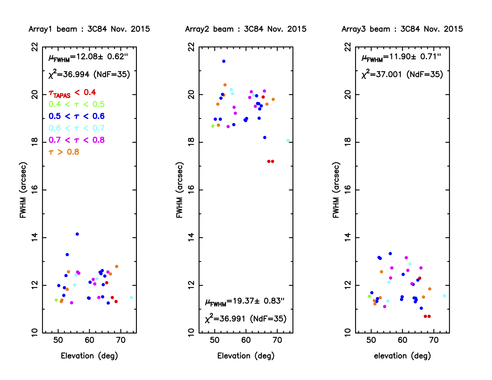
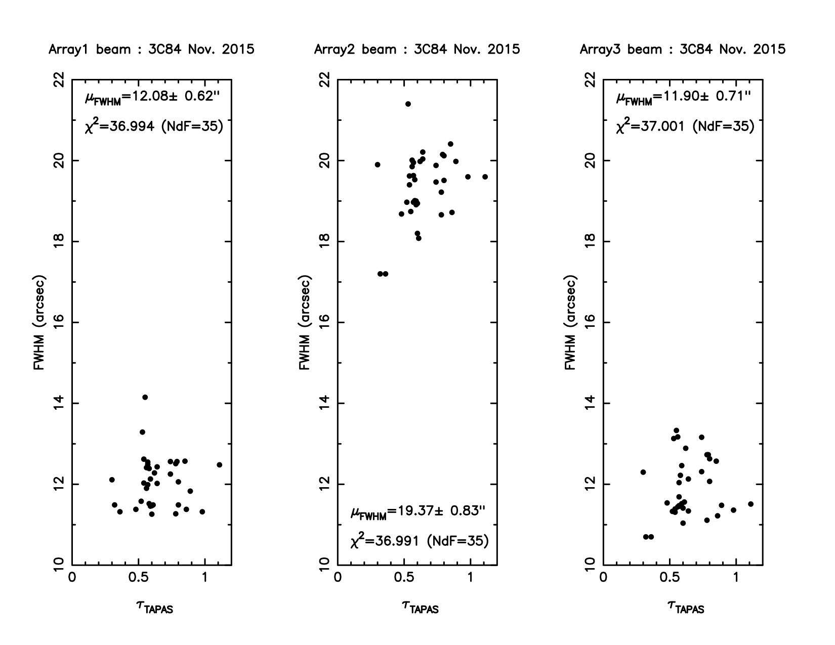
Analysis of 37 observations of the quasar 3C84 (nk_otf and nk_point lissajous). Data (measured FWHM's) are plotted versus elevations as well as versus opacities for the three arrays. Statistics are printed in figures. There is no striking dependence of FWHM on these two paremeters. For each array, fluctuations of FWHM around its mean are gaussian as shown by non-normalized chi2 for number of degrees of freedom NdF.
Preliminary findings
- The main beam (the Gaussian part) seems with a normal width aka 11", 17" (but only in single-pixel analysis). Blind 2D Gaussian fits to the maps result in broader beams of 13", 19.5" (see Table below).
- The quadrupod holding the secondary gives clear diffraction marks as a faint cross at about -30dB, visible in all Mars scans. Uranus and 3C83 are not bright enough to reach -30dB. To go deeper, we need Saturn or Jupiter maps.
- In between, there is a large near-side lobe, especially at 2mm (but also visible at 1mm), that shows up as a rectangular pyramid-like shape at the 10% level, the origin of which is unknown. It seems to scale with wavelength. It was not so apparent in NIKA. Therefore the quality of the dichroic is not at the center of this issue.
In fact the rectangular shape of the first side lobe is known and expected from optical simulations (I didn't communicate about it until now). It is due to the combined diffraction on the primary mirror and the quadrupod holding the secondary mirror. However, the expected level of this side lobe is ~2% of the central peak when the focus is correct, and it increases to 10% if the defocus along the Z axis of M2 is ~0.7 mm. See the figure at the bottom of this page for more details. -SL-
For comparison, see the NIKA-1 beam maps in Fig.8 of Catalano+2014 and in Fig.8 of Monfardini+2011.
- The following table shows the FWHMs derived from 2D-Gaussian fits to the observed emission.[Note that if the error beam is included in the fit, the main beam narrows down]
Source
Date/Scan
HPBW
HPBW
1mm
2mm
Mars
20151030s73
12.9
19.3
Mars
20151031s88
12.7
19.6
Uranus
20151029s217
14.5
19.5
Uranus
20151030s174
13.2
19.7
3C84
20151030s51
14.3
19.4
- Will redo the greg plots of the beams, together with 2D Gaussian fits, and create radial averages, once the coordinate problems in the IDL fits data have been solved. This is actually on the way. (CK 4-Nov-2015)
Maps seem too small ! Comment by RZ
It seems to me that one important problem was not taken into account while analysing the beams: the incorrect coordinates during roughly 2 sec at beginning of each subscan (see e.g. daily reports, Oct 29-30 and my other reports during the past runs). More recent examples on 3C84 are shown below.
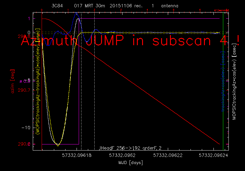
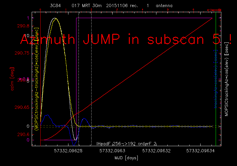
In blue are shown the available tracking errors, in white the correct values. How large is the error of the coordinates depends on the elevation and the scanning speed. For usable obs. parameters the values may reach even 30arcsec ! Though this scan was not used for the beam analysis the shown examples (i.e. 20151029s95 & 96, 20151106s17) are representative for all OTF observations.
In such a case the general condition for map size in the scanning direction in case of not perfectly stable receiver:
mapSize = sizeOfSource + sizeOfFOV + base
must be changed to:
mapSize = sizeOfSource + sizeOfFOV + base + 2*sizeOfErrorZone
sizeOfSource is the diameter of the to be analysed error beam (read from the attached figures 1 to 2arcmin), sizeOfFOV is 6.5arcmin, base should be at least 3*HPBW, sizeOfErrorZone is ~2sec*scanning velocity, i.e. ~2arcmin.
This shows that only the 20arcmin maps satisfy the above condition. For smaller maps the pixels which appear at map edges must be excluded from the analysis. As the array rotates with elev in (azim,elev) different pixels are affected. (RZ, 6-Nov-2015)
Theoretical beams from Zemax simulations (for comparison, SL 2015-11-02 and 04)
By design of the optics the image plane is as flat and aberration-less as possible, but for such a big FoV and given the constraint on the number of lenses we can't avoid that the optimal focus surface on the image plane has a residual bowl shape, which correspond to 0.4 mm amplitude of M2 along Z between the central pixel and an edge pixel (6.5'diameter ring). But the distance along the M2 Z axis between the best central and the best average is 0.2mm (= best at the 4' diameter ring). As a consequence there's a Strehl ratio (~beam peak amplitude) variation of 10% at 1.2mm and 4% at 2mm along the FoV if the focus is on the central pixel, but these values are reduced to less than 3% at 1.2mm and less than 1% at 2mm if the focus is on the 4' diameter ring.
The images below show the 1mm band beam shape in false color and logarithmic scale (top), and a cross section in linear scale (bottom), for the central pixel (left), an edge pixel at Y=6.5' (center) and an edge pixel at X=6.5' (right) for various position of the focus (note the 2mm band beam shape is identical to the 1mm beam, but it is larger and twice less sensitive to the focus variation). I also added plots of the Strehl ratio along the FOV on the X axis of the image plane from 0 to 3.25' radius. For both the focus on the central pixel, or the best average, we are still significantly above the diffraction limit; in the worst case of 10% decrease of the Strehl ratio (e.i. focus on the central pixel), we convolve a 0.2 mm radius aberration spot with a 1.7 mm radius Airy pattern for the central pixel and a 0.8 mm radius aberration spot with a 1.7 mm radius Airy pattern for the edge pixel, while the aberration spot variation is at most +/- 0.1 mm on the image plane for the best average focus. Thus, the beams are always acceptable to maintain the angular resolution, but less optimal in terms of contrast on the image (e.i. dynamic, e.i. gain) if we focus on the central pixel versus the best average focus.
Table of the HPBW for the central and an edge pixel, at central focus an best average, based in Zemax simulation (linear plots below) and pixel physical size (illustrate well that the effect of focus inhomogeneity on HPBW is much smaller than on the Strehl ratio, and more importantly much smaller than the variations on real measurements due to other factors):
Central wavelength
1.16 mm
1.92 mm
HPBW central field with focus on central pixel
9.57"
15.41"
HPBW edge field with focus on central pixel
9.86"
15.69"
HPBW central field with best average focus
9.60"
15.42"
HPBW edge field with best average focus
9.75"
15.61"
One question is the size of the main beam (resolution) the other is the efficiency of the main beam (contrast). The main beam efficiency apparently changes quite a lot across the FoV depending on the z focus. This is of course a problem for interpretation of the data (-> astrophysics). Another problem however appears before this, it concerns the data processing: as the SNR of the data increases during the processing by factors even >100 (mainly because the correlated signal (mostly the sky noise) can be filtered out) the change of the main beam efficiency across the FoV sets in general very severe limits for the quality of the processing !
Further, in practice it will not be easy to put the focus to the "best value at the 4' diameter ring" using the focus on the central pixels + offset (every measurement has an error, for the focus it is hard to get better than ~0.1mm) and - of course - the focus DOES change with time. The normal situation therefore will be that most pixels will have much larger error beams than in the optimal case. (RZ 9-Nov)
To improve the overall beam efficiency for all pixels, we could add a constant offset to each focus, i.e. to the measured best focus value of the central pixels at a given time. This constant offsets could come from the optical simulations and the predicted variation of the Strehl ratio. (CK 10-Nov)
Figures below: 1mm band beam in logarithmic scale (top), and a cross section in linear scale (bottom), for the central pixel (left), an edge pixel at Y=6.5' (center) and an edge pixel at X=6.5' (right). Strehl ratio along the FOV on the X axis of the image plane from 0 to 3.25' radius.
- Focus optimized on the central pixel:
- Focus optimized on the 4'FOV ring = best overall focus on the array = best central + 0.2 mm:
- Defocus: best central - 0.5 mm:
- Defocus: best overall - 0.5 mm:
- Defocus: best central + 0.5 mm:
- Defocus: best overall + 0.5 mm:
Beam Profiles (NB)
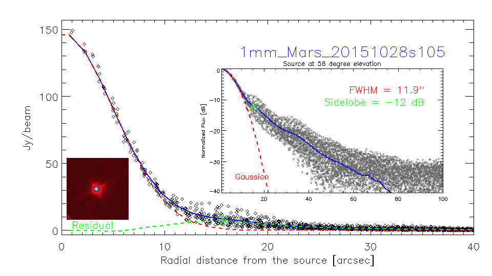
- Below are 1-D profiles extracted from a few maps on Mars and Uranus. The maps were generated off-line with CM-kids-out and a mask of 60" in radius. No opacity correction for the time being. The square feature mentioned above, and visible on the embedded image below, is most likely a combinaison of the first side lobe and the first error beam (although the first error beam is ~60" wide at a level of 0.2%) [I'd call this error beam. (CK)] and it appears as a plateau in the 1-d profiles. The higher scatter where the plateau is means that this feature is not axisymmetric, possibly due to the quadrupode signature. The profiles are also fitted with a 1-d gaussian, and the FWHM displayed on the plot. This FWHM might be marginally increased because of the first side lobe that enlarges the beam pattern (right click the image to open in other window to see full scale). By putting more weight on the central part of the beam, the 1-d gaussian fits better the main beam and gives FWHMs typically 0.5" (1") thinner at 1mm (2mm). The plots below show that the gaussian fit residuals are negligible within the main beam. Note that nk_map2fits.pro only outputs images for the first 2 arrays, so the second 1mm array is missing from this analysis. Some of these profiles were derived from the same scans as displayed at the top of this page. Such profiles can be generated on request for your favourite beam maps.
Fits for Beam Maps, radial profiles, integrals, NIKA2-EMIR (October-2015, FXD-NP, CK)
- Beam maps are made for some scans in fits format (some plots available too): sftp nika2 /Archeops/N2R1/Product/Test_beams.zip
- A tgz archive with resulting beam maps and radial profiles is available here:
https://cloud.iram.es/index.php/s/UI2VWI6gPNKjNgl
The maps have been centered and normalized. A 2D-Gaussian has been fitted to the main beam, and the radial average plotted in comparison with the fitted main beam.
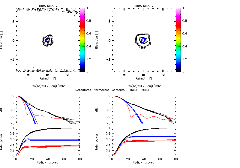
Overlay of the six best contour maps of Mars and Uranus taken in October, together with their radial profiles (black). The fitted Gaussian main beams are shown in blue. Left: 1mm, Right: 2mm. The contour maps agree quite well, and, hence, the radial profiles agree very well, down to -40dB and up to a radial distance of 70", independent of date and source, for Mars, Uranus, and also for 3C84. In red shown are radial profiles at 145 and 250GHz, which are deduced from lunar scans with EMIR and include the main beam and the three modelled errorbeams (cf. errorbeam report 2013).
- NIKA-2 HPBWs (from Mars) are 20.9" at 2mm and 13.0" at 1mm, broadened relative to EMIR.
These values are considerably larger than the arithmetic average of the individual beams, are therefore representative for problems of data processing, not of the NIKA2 optics. For the arrays 1 & 3 correct processing gives HPBW ~11.4*11 arcsec for the main beam (anomalous refraction and out-of-focus effects, i.e. ellipticity of the final beam, cannot be removed). Further problem is the large focus offsets between the 1mm & 2mm arrays. As a consequence it is impossible to get the correct beams for both wavelengths in one observation. (RZ, 2015-12-08) To my mind, we should do a selection of the best scans (focussed on 1mm, focussed on 2mm, processing them in the best possible way, including also the November data. (CK, 2015-12-09)
- EMIR HPBWs are 16.6" at 145GHz, 9.6" at 250GHz, and 9.2" at 260GHz.
NIKA2 consistently shows a strong errorbeam at -10dB and below, much stronger than what has been seen with EMIR. Note that the NIKA2 and EMIR illuminate the 30m surface differently. EMIR illuminates the dish with a Gaussian with an edge taper of about -14dB, while NIKA2 illuminates a fraction of the dish with a rectangular function (CHECK). Lunar scans were taken under very best sky conditions during night time. (The center frequency of the NIKA2 1mm array is about 260GHz!)
- For NIKA2 at 2mm, 30% of the power integrated within a radius of 80" comes from the errorbeams, i.e. 70% comes via the main beam. At 1mm, 40% of the power integrated within a radius of 80" comes from the errorbeams, i.e. 60% comes via the main beam. For this integration radius and for EMIR the fractions from the main beam are higher. CHECK

