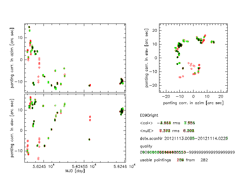
Here are a few preliminary plots performed on this scan.
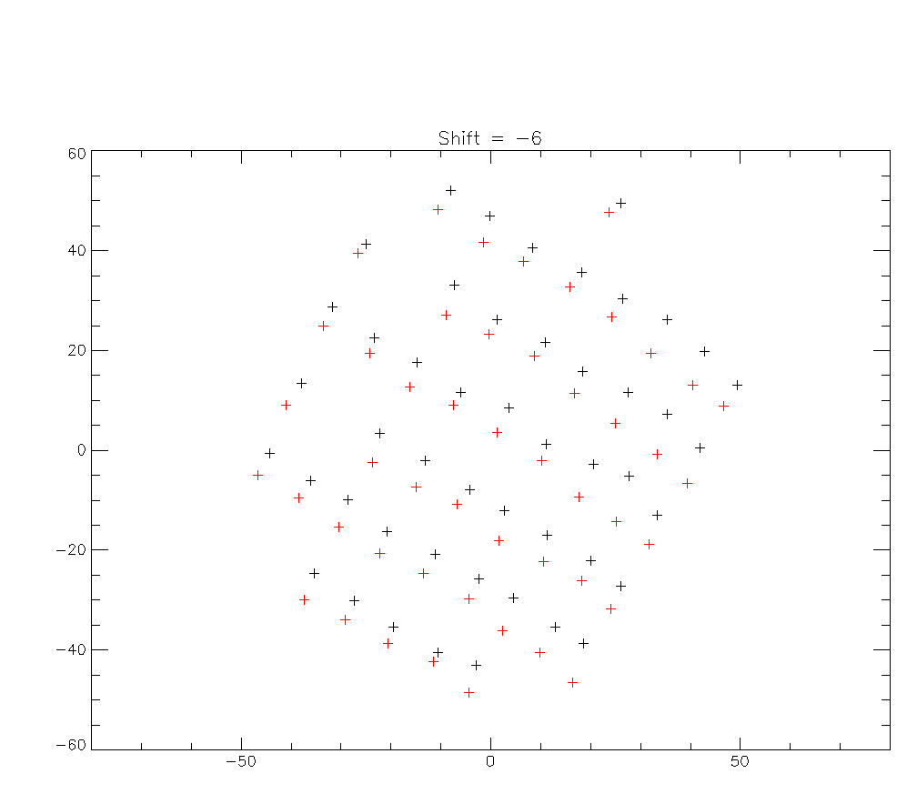
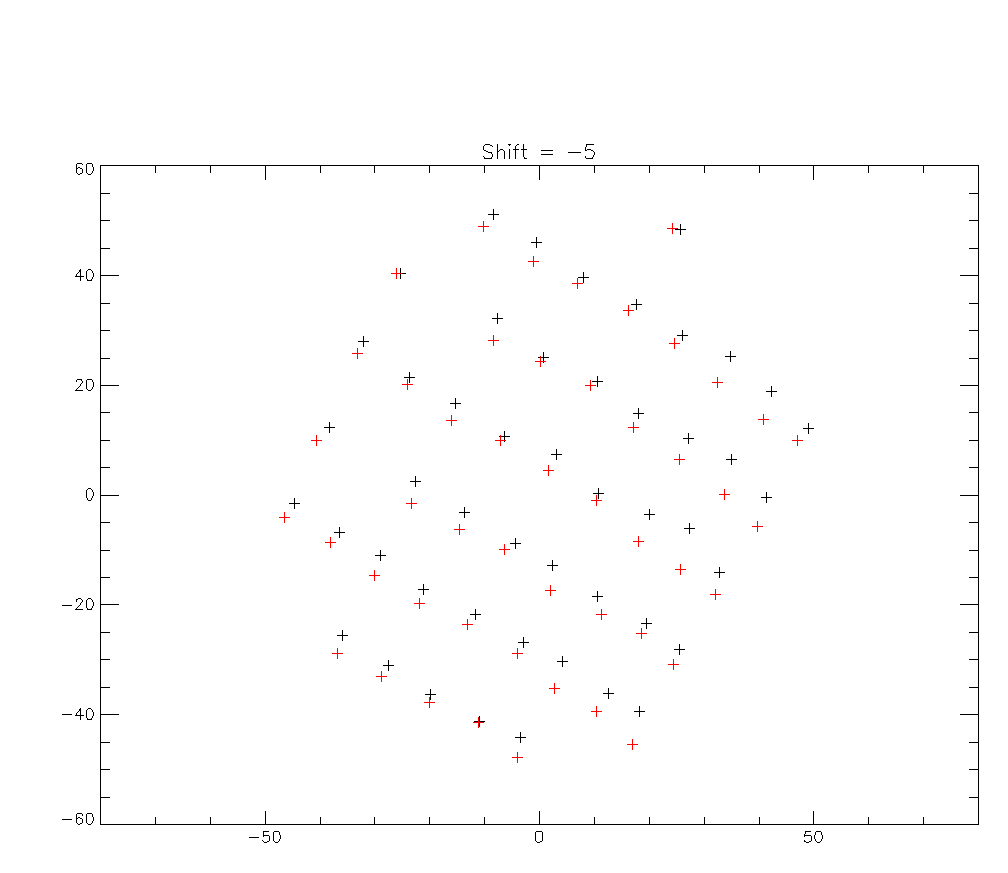
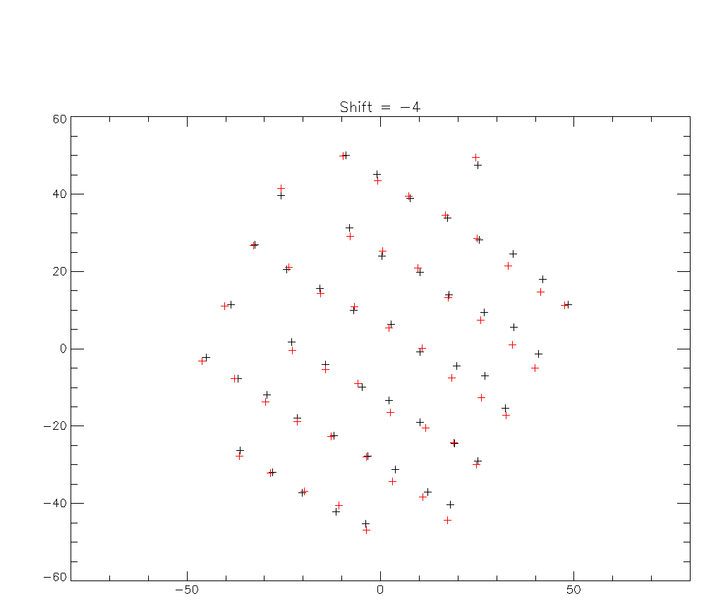
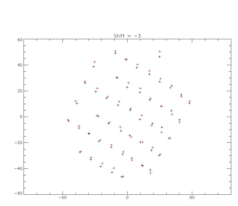
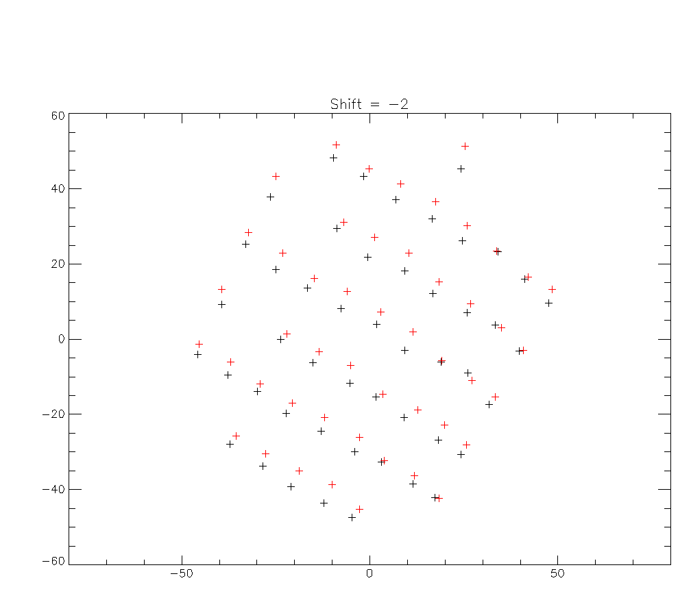
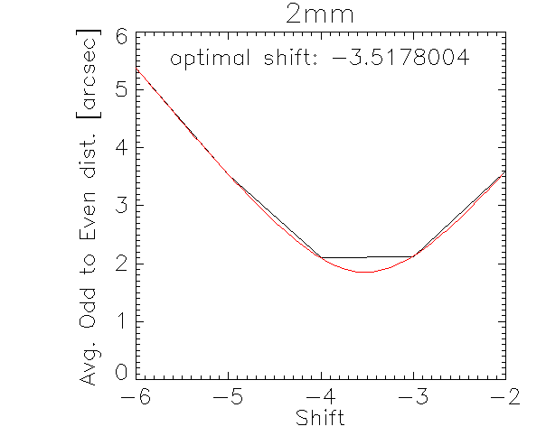
First, I investigated the zig-zag effect and found that a correction of 3 to 4 samples could improve things. This needs to be further understood and corrected at a lower level of TOI processing. Here are a few plots of the beam centroids of valid pixels near the center of the 2mm matrix computed with only the forward scans and only the backward scans for various shifts of the timeline. The last plots shows a fit of the total distance between beams as a function of the shift and shows an optimum at -3.5. We choose to apply a correction of -3 in the following.
Here are the first OTF_Geometries derived from this scan. Beam contours are 1FWHM, colors correspond to the peak amplitude of the gaussian beam fit, normalized to the median of the peaks. This is intended to ease real time comparison between future similar scans. As can be seen, the rows and columns of the matrices are not as orthogonal as they should and beams are systematically elongated in the same direction. I still don't know why.
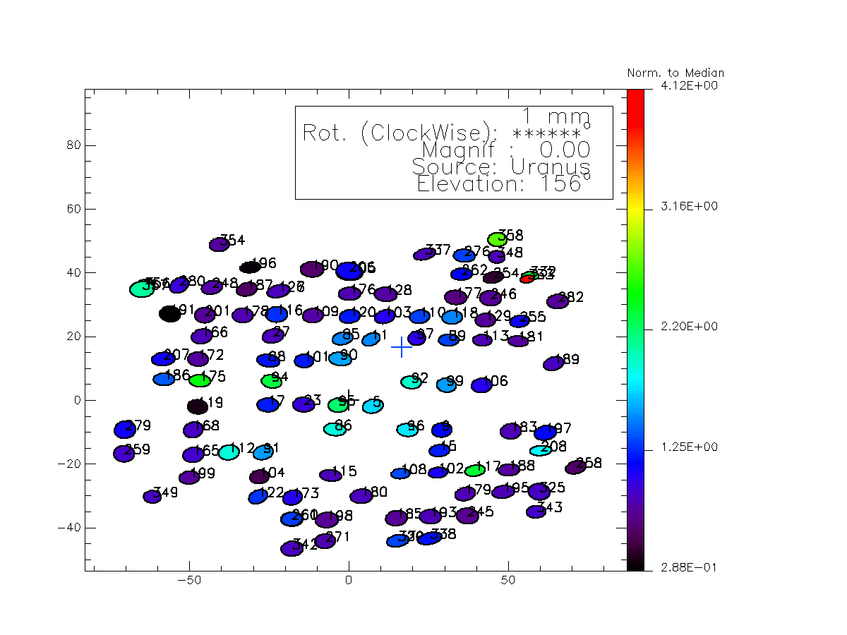
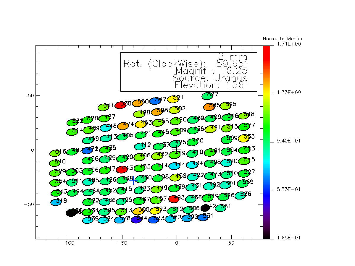
There has been discussions regarding the .fits building. In particular, the issue of the cos(elevation) to be included of not for the offsets was not clear. Adding it by hand with the average elevation of Uranus, things greatly improve:
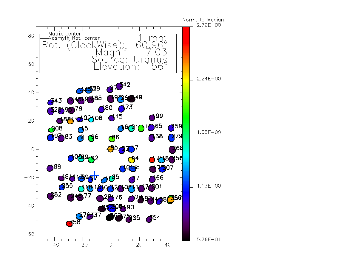
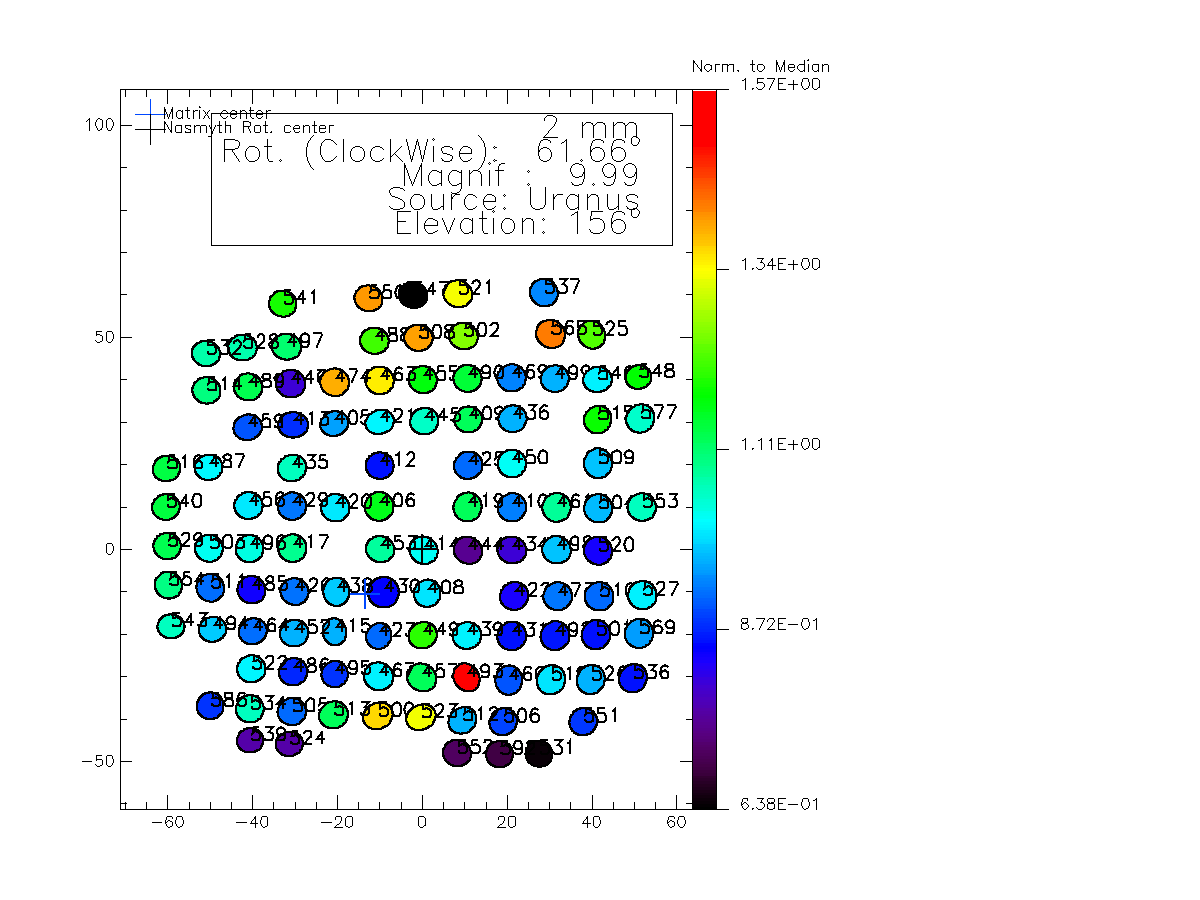
RZ, 15 Nov 2012
I could understand some of the problems above if the evident pointing problems with EMIR were not internal to EMIR (e.g. mirrors). The figure EMIRpointCorr_13-14Nov below gives a summary. The pointing corrections make a circle with ~10arcsec radius (upper right-hand plot).
