240 GHz band
Array: Same as runs 4,5,6. NICA 8e, 20nm Al IRAM (no bondings across-the-line). LO 1.955GHz, power per tone -52dBm (at cryostat input incl. 2m flex cables, assuming 2dB between niv5 and niv6, see later).
Pixels: pitch 1600 x 1600 micron. 224 pixels on design (16x16 array minus the corners). 196 identified resonances (about 20 more are higher in f, out of the NIKEL band), about 180-190 useful pixels. 40 OFF-resonance. Total number of channels 236.
Cold electronics: SiGe Caltech amplifier "Florence" (gain 40dB, 1dB compression point 0dBm integrated power, Noise T around 6K).
Warm electronics: NIKEL01. RF source 192.168.1.196 (IFR 2024 Leasametric). 0dB attenuation at cryo IN. DAC 20,23,20,25,32; niv 6 (measured -54dBm per tone at cryo input, including 2m flex cables, FOR NIV 5). LO modulation 8kHz. VLF2600 low-pass filter at cryostat input.
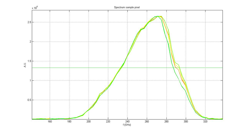
Optics and spectrum: Same optical configuration as run 4 and 5. Except one filter (LPE 9cm-1) less compared to run 6. Also, using corrugated lenses (were smooth in previous runs) at 4K and 100mK. Spectrum peaking at 270 GHz (FWHM=230-290GHz).

Figure: Response spectrum measured in Grenoble on the 1mm array used for run7. Run PT33 (for more information see ELOG).
ASCII data for the spectrum on the pixel 1 (frequency(GHz), Response (AU)): pix1_1mm.txt
FITS interferograms data: interf_1mm.fits
150 GHz band
Array: NICA8f1, 18nm Al film made at IEF, litho PTA. LO 1.363GHz, power per tone -55dBm (at cryostat input incl. 2m flex cables).
Pixels: pitch 2305 x 2305 micron. 132 pixels on design (12x12 array minus the corners). 128 identified resonances, at least 125 useful pixels. 40 OFF-resonance. Total number of channels 168.
Cold electronics: SiGe Caltech amplifier SN 84 (unchanged), (gain 40dB, 1dB compression point 0dBm integrated power, noise T around 4K).
Warm electronics: NIKEL02, RF source 192.168.1.192 (IFR 2025 IRAM), 3dB attenuation at cryo IN, DAC 20,23,20,27,35; niv 5 (measured -55dBm per tone at cryo input, including 2m flex cables). LO modulation 5kHz. VLF2250 low pass filter at cryostat input.
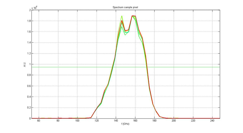
Optics and spectrum: Same optical configuration as run 4,5,6. Just using corrugated lenses (were smooth in previous runs) at 4K and 100mK. Spectrum peaking at 146 and 160 GHz.

Figure: Response spectrum measured in Grenoble on the 2mm array used for run 7 (FWHM=135-170GHz). Run PT33 (for more information see ELOG).
ASCII data for the spectrum on the pixel 1 (frequency(GHz), Response (AU)): pix1_2mm.txt
FITS interferograms data: interf_2mm.fits
