|
Size: 10772
Comment:
|
Size: 17677
Comment:
|
| Deletions are marked like this. | Additions are marked like this. |
| Line 1: | Line 1: |
| #acl hermelo,CarstenKramer,NicolasBillot,SamuelLeclerc:read,write,delete,revert,admin Default = Observing session = Observations are carried from a dedicated pool account (ask the AoD for the login information). Each project has a folder within the home directory of the pool account with instructions on how to proceed. Read carefully the README file before to start. For example, the file [[attachment:README_193-13.txt | ~/193-13/README_193-13.txt ]] shows you how to observe the project 193-13. |
#acl PabloGarcia,CarstenKramer,SamuelLeclerc:read,write,delete,revert,admin Default = Observing with NIKA2 = |
| Line 13: | Line 7: |
| '''[[ http://www.iram.es/IRAMES/mainWiki/FrontPage | Go to the Front Page ]]''' | '''Go to the [[http://www.iram.es/IRAMES/mainWiki/Continuum/NIKA2/Main| NIKA2]] main page.''' |
| Line 17: | Line 11: |
| == Choose a project == First log into the [[https://pools.iram.es | Pool data base]] (ask the AoD for the login information) and click on the GISMO/NIKA tab. {{attachment:PoolDatabase.png | Pool data base | width=1000 }} Projects have different priorities from 6 (highest priority) to 1 (lowest priority). Green color indicates that the project is '''scheduled''', orange that the project is '''on hold''', and red that the project is '''finished'''. Only green projects should be observed. To check the visibility of these projects go to the visibility tab: {{attachment:Visibility.png | Visibility plot | width=1000}} The red vertical line corresponds to the current time (UT). In this example there are four priority 5 projects. Project 077-13 is not visible at the current time. Project 079-13 is close to the low elevation limit so it is a bad option. Since project 103-13 sets first, you should first observe this project. After 2-3 hours change to project 100-13. In case that none of the priority 5 projects have weather requirements (see the README files) compatible with the current conditions, go for priority 4 projects and so on. |
Computer terminals for observations NIKA2 pool observers have at their disposal two terminals for observing operations (also accessible remotely via a VNC server). Terminal mrt-remote:32 is devoted to observing tasks with NIKA2 and the terminal mrt-remote:30 is reserved for EMIR backup observations. In the mrt-remote:32 terminal the observer will find up to 7 active desktops. The desktop 1 contains a terminal with a running session of the observer user interface to the control system of the IRAM-30m telescope, nicknamed paKo (see next Section), the paKo display (light green window) with relevant information on the status of the telescope, an auxiliary terminal, and the Antenna Data Stream. A screenshot from a previous pool session (current pool account is "nikaw-23"; ask the AoD/operator for the login information) illustrates what desktop 1 looks like: {{attachment:t32_desktop_1.png||height="700"}} From the prompt in an auxiliary terminal in desktop 1, the observer can access the contents of the root folder of the pool account. It contains as much as folders labeled in the form XXX-YY as projects are scheduled. This is a unique identification format provided by the IRAM’s Project Management System and coincides with the account name of the project. Inside each project folder, the observer will find, at least (i) a setup file (setup*.pako), (ii) a source file (*.sou), (iii) the observing script(s) (*.pako), and (iv) a text file with the project instructions for the observers (README*). In this NIKA2 Pool folder, the observer will also find a couple of wallpapers reminding most of the NIKA2 commands explained on this site. For viewing them use the command "display nika2_wp[1,2].jpg" from this auxiliary terminal. The remaining desktops of terminal mrt-remote:32 are reserved for the XEphem windows, as well as the [[https://publicwiki.iram.es/PIIC|PIIC]] and IDL quick-look (QL) monitors which are continuously running during the NIKA2 Pool. All of this is referred to below. Further information will be provided to the observers at the beginning of the observing sessions. == Starting paKo == In case of need, to start the paKo session for regular observations, log into the pool account "nikaw-23", open a terminal and type: {{{ $ ssh -XY nikaw-23@mrt-lx1.iram.es $ goNIKAnew $ PAKO> set project [nikaw-23 or test] $ PAKO> set dosubmit yes }}} Now you are ready to start observations. == Observations queue == To check what is currently in the observation's queue, open a terminal and type: {{{ $ ssh -XY nikaw-23@mrt-lx1.iram.es $ observationQueue & }}} This will open a file browser with a list of all the observation's files commanded, which are waiting to be executed by the telescope's system. To remove any observation's file from the queue, right-click on the corresponding xml file and select "delete". The display will be automatically refreshed. ## Check the [[https://mrt-lx1.iram.es/mainWiki/NcsUG | NCS user guide wiki]] for more obs* commands. == Starting XEphem == XEphem is the software currently used at the IRAM 30m telescope to keep track of the position of astronomical sources in the sky. To (re)start XEphem, open a terminal and type: {{{ $ slogin mrt-lx3 $ xephem & }}} On the main Xephem window, click on the tab "RT" (for real-time) to activate source tracking in this software. Then, click on the tab "View" and open the "Sky View". {{attachment:Xephem_1.png||height="400"}} {{attachment:Xephem_2.png||height="400"}} <<BR>> A map similar to the one shown below will appear. The "telescope icon" shows the coordinates the telescope is pointing at. The filled white circles are the pointing sources. The size of the circles is proportional to the flux of the target. Use the sliders on the border of the map for scaling the field of view. {{attachment:Xephem_3.png||height="900"}} <<BR>> To load the sources catalog of your project, click on the tab "Data" and go to "Files". In the new window go again to "Files" and select the catalog of the project that you plan to observe. {{attachment:Xephem_4.png||height="400"}} {{attachment:Xephem_5.png||height="400"}} <<BR>> Ask the AoD or the Operator for further details. == Starting PIIC == PIIC-QL monitor has been provided to process continuously the NIKA2 data. To start it, first ask the AoD to start the production of NIKA2-imbfits required to reduce the data with PIIC. {{{ $ ssh -XY nikaw-23@mrt-lx3 $ cd ql $ gagpiic $ piic @monitorX }}} with X = 2pf, for 2 mm-pointing/focus monitoring only, and X = 1, 2m, 3, the instrument array to be monitored. == Starting the NIKA2 IDL pipeline == Optionally, to have the IDL pipeline continuously processing observations as they are produced, open a terminal and type: {{{ $ ssh -XY observer@nika2-a (ask the AoD for the password) $ IDL IDL> nk_rta, scanID (e.g. '20201019s132') }}} where scanID is the corresponding identifier of the observation (as shown in the example) in the format YYYYMMDDsXXX, where YYYY is the year, MM the month, DD the day, and XXX the scan number. == Pointing == Under standard conditions, pointing corrections of the IRAM 30m telescope should be done every hour or a bit more with good stability (see below), except around dusk and dawn when more frequent pointing corrections may be necessary. In order to correct the pointing of the telescope in a given part of the sky choose a nearby pointing source (using e.g. XEphem) and type: {{{ PAKO> source 0133+476 /cat * (or "iram-J2000.sou" or "pointingIRAM30m.sou", or "CalibNIKA.sou" for secondary flux calibrators) }}} Now launch the '''nkpoint''' script: {{{ PAKO> @ nkpoint mode }}} where the keyword "mode" can adopt the values '''b''' for bright sources and '''f''' for faint sources (the '''l''' option for very faint sources that require the Lissajous pattern is no longer used). To obtain the pointing corrections, use the results given by the 2pf PIIC monitor. Supplementarily, PIIC monitors 1 and 3 show the pointing corrections based on 1 mm data. Alternatively, you can process the corresponding scan with the IDL pipeline: "IDL> nk_rta, scanID". Once the pointing scan is processed, enter the new pointing corrections in azimuth (PnewX) and in elevation (PnewY) shown on the IDL prompt of the NIKA2 pipeline: {{{ PAKO> set pointing PnewX PnewY }}} An example of PIIC-QL main plot of a standard pointing scan is shown in the following picture. Pointing correction, a proxy of the beam size (main-beam FWHM at 2 mm wavelength), and other data are highlighted: {{attachment:pointing_piic_example.png||height="700"}} <<BR>> Alternatively, the corresponding pointing scan number can be processed by the IDL pipeline by simply typing: {{{ IDL> nk_rta, scanID (in the form 'YYYYMMDDsX') }}} The pipeline will recognize a pointing scan and the correction will appear in a while. According to [[https://arxiv.org/abs/1910.02038|Perotto et al. 2020]], lower limits of beam size (FWHM) with NIKA2 are 11.1 arcsec (1 mm, arrays 1 & 3 combined) and 17.6 arcsec (2 mm; array 2). If you happen to have noticeable broader beam sizes, (i) probably a new focus correction would be needed, or (ii) the pointing source is not a point-like one in the sense of the main beam size, or (iii) the FWHM is measured on scans acquired in the late afternoon when the main dish of the antenna is warmed and unrelaxed, or (iv) anomalous refraction/high-frequency atmospheric instabilities could be affecting the pointing scan. In case of doubts, ask the AoD. == Focus == The focus needs to be monitored and it needs to be corrected online. This should be done every two hours or so (~3h during very stable night-time conditions, ~1h or less near sunrise and sunset) in the Z direction. To check the quality of the focus run: {{{ PAKO> @ focusOTF-Z fz }}} Currently, this script will carry out 5 foci measurements in Z direction within a 1.6 mm range, centered at the fz value. Telescope focus for NIKA2 is currently around 0 to +1 mm in standard conditions. To obtain the focus corrections, use the results given by the 2pf PIIC-QL monitor. Supplementarily, PIIC-QL monitors 1 and 3 also show focus corrections from 1 mm data. It gives the best focus corrections from an order-2 fitting of the observed peak flux, and two different parameters from a 2d-gaussian fit of the source used for this purpose. Under expected conditions, these values should broadly converge. If this condition is not met, the average of the two mutually consistent values could be adopted as a focus correction. An example of a typical result of a focus sequence from the PIIC-QL monitor (2 mm) looks as follows: {{attachment:focus_piic_example.png||height="800"}} <<BR>> Conversely, if the fz value is not a good pivot for the focus sequence or under stable weather conditions, the focus results would be like the plots in the figures below: {{attachment:focus_piic_bad_example_2.png||height="400"}} {{attachment:focus_piic_bad_example_1.png||height="400"}} <<BR>> In general, after applying the new corrections, good fitting results are expected, but it is always safe to repeat pointing and focus observations once again to confirm whether the beam geometry is properly measured. Alternatively, the corresponding scan number can be processed by the IDL pipeline: {{{ IDL> nk_rta, scanID1 (for measurement 1) IDL> nk_rta, scanID2 (for measurement 2) IDL> nk_rta, scanID3 (for measurement 3) IDL> nk_rta, scanID4 (for measurement 4) IDL> nk_rta, scanID5 (for measurement 5) }}} Then, all measured foci need to be processed together by the "nk_focus_otf" routine of the IDL pipeline to perform the best focus fit in terms of the measured Flux, beam FWHM, and beam ellipticity of the KID's. This can be achieved by running the following instruction in the IDL prompt: {{{ IDL> nk_focus_otf,'YYYYMMDDs'+strtrim(SCANNUMBER+indgen(5),2) }}} where the ScanID is in the format YYYYMMDDsSCANNUMBER (e.g. '20151019s132'). Once the "nk_focus_otf" routine has finished, check the focus correction values displayed in the IDL prompt under "Fluxes" for the three arrays (A1, A2, & A3) and calculate the average value that will be used to correct the focus. Enter the new focus value (Fnew) as follows: {{{ PAKO> set focus Fnew }}} == Daily calibrations == === Beam maps === This kind of scan is to be done once a day or every two days. It takes ~25 min, so to avoid accounting for the time spent on your project think about changing the project to: {{{ PAKO> set project nikaw-23 }}} Beam maps are designed to ensure the source is moved over all the detectors of the array, in order to characterize and calibrate them (field of view geometry, flat field, stability, etc). The aim is to calculate the actual pixel offsets in the focal plane (see figure below). Low opacity and good stability are mandatory, and Uranus, Mars (if apparent size is < 10”), or 0316+413 (3C83) can be used for that. To obtain a beam map go to a primary calibrator, get focus/pointing corrections, and launch the '''beammap1scan99sub.pako''' script in the normal paKo session: {{{ PAKO> @ beammap1scan99sub (to produce 99 sub-scans, standard paKo version) OPTION = a (ENTER OPTION: a = Az. scan, e = El. scan, l = lower than 60° in El., h = between 60° and 70° in El.) W-OTFMAP /TOTF, value 12.0 implies /speed 65.0 outside standard range 0.0 to 60.0 W-OTFMAP, WARNING--CONDITION: Elevation must be less than 69.03 [deg] OTFMAP 780''x 470.4'' (step 4.8) > Number of subscans: 99 > Scanning speed: 65 arcsec/sec > Time per subscan: 12 sec > Execution time: 23.1 min }}} {{attachment:beammap1scan99sub.png | Beammap 99 sub-scans | width=500 }} Don't forget to set back to your project once the beam map is done! === Flux calibration scans === If conditions are stable and the beam sizes are close to the expected values, get flux calibrations during the day and the night as possible, taking advantage from a focus sequence on primary (Mercury -when is not so close to the Sun-, Mars -if the apparent size is < ~10 arcsec-, Uranus, Neptune) or secondary calibrators (NGC7027, NGC7538, CRL2688, CRL618, MWC349, W3OH, ALFORI in the CalibNIKA.sou catalogue). The AoD will ask the observer for this kind of scan, which takes ~4 min: {{{ PAKO> set project nikaw-23 }}} To run a flux calibration with NIKA2, select the desired standard source and type in paKo: {{{ PAKO> @ calib_1scan }}} === Skydips === This kind of scan is to be done two to four times a day. It takes ~6 min, so to avoid accounting for the time spent on your project think about changing the project to: {{{ PAKO> set project nikaw-23 }}} To run a skydip with NIKA2 type in paKo: {{{ PAKO> @ skydip }}} The script will perform 11 measurements (30 [s] tracks) at different airmasses wrt. the position Az = 180°, El = 55° in the HORIZON coordinate system. The skydip takes ~6.4 minutes to be finished. Don't forget to set back to your project once the sky dip is done! == Science targets == Observations of science targets are performed via on-the-fly (OTF). '''Observers may want to scan only in Azimuth, as scan directions other than Azimuthal induce instabilities/drifts especially for NIKA2, and increased noise due to: change of airmass; reaction to telescope acceleration; coupling to electric/magnetic/acoustic signals.''' In any case, the prepared scripts allow for a variety of scanning directions. For example, for a 10'x15' OTF map, with a position angle of 25 degrees, a tilt angle of 0 degrees (both measured '''anticlockwise'''), in equatorial coordinates (radec, for the HORIZON coordinate system set '''azel'''), just type: {{{ PAKO> @nkotf 10 15 25 0 20 40 radec }}} This command will produce a scan pattern as follows: {{attachment:otf_example.png | OTF scan | width=500 }} A sequence of several scans can be loaded using a script containing a sequence of '''nkotf''' maps. For example, the script [[attachment:observe2_NGC4449.txt | observe_NGC4449.pako]] combines several 10'x15' OTF maps at different PA and tilt angles in the horizontal coordinate system (azel). Note that in general, it is better to have the longer direction along the subscan to minimize the time loss due to overheads between subscans. Also for baseline subtraction in the data processing, it's always better to set a subscan length longer than the usable map you wish to have (typically ~1' more than the usable map; the optimal value depends on the map size and scanning speed). Scanning in azimuth is better for sky noise subtraction, but the best scanning strategy depends on your source shape and its az-el coverage during the integration time. == Atmosphere stability issues == At the IRAM 30m telescope the opacity at 225 GHz, tau_225GHz, is recorded by a dedicated radiometer and processed (see [[https://www.iram.es/IRAMES/weather/tauMeter.html| opacity monitor]]). From that, the precipitable water vapour, pwv = [tau_225GHz – 0.004]/0.058, can be estimated. These opacity estimations are plotted together with model (AM) predictions at different time scales, and they can be seen by accessing the [[https://weather.iram.es\opacity records & forecasts]]. This is a valuable tool for the observers/AoD for fine observation planning. Together with opacity and the atmospheric transmission factor (modelled as exp{-tau_225GHz * sin[El.]}), the stability timescale of the atmosphere during the observations affects the baseline subtraction and the mean rms noise of a given scan. A rule-of-thumb that the observer can use as a quick approach is to have a look at the upper left plot that results from the PIIC-QL pipeline at 2 mm. As an empirical rough approach, if peak-to-peak variations of the timelines given in such a plot are below +/- ~6 Jy/beam, we can say that the atmosphere is stable in the sense of NIKA2 scan. For each project, a prescription about this issue is usually provided by the PIs of the projects to the observers. For the latter ones, it is a good practice to provide an estimation of the p2p variations, and complementarily the rms of the raw timelines, for selected scans in the logsheet of TAPAS. If we translate this rule to the 1 mm array, the threshold of these variations is -in general, but not always- about a factor 3 the value used for the 2 mm band. The following PIIC-QL plots are representative of high atmosphere stability. The first one corresponds to a scan for a pointing correction, and the second one to a science scan: {{attachment:stability_1.png||height="400"}} {{attachment:stability_2.png||height="400"}} <<BR>> |
| Line 41: | Line 275: |
| == Starting PaKo == To run the observations at 30m telescope it is necessary to start a !PaKo session. First log into the mrt-lx1 machine: {{{ $ ssh -X pool_account@mrt-lx1.iram.es (ask the AoD for the name of the pool account and the password) }}} Then start PaKo: {{{ $ gopako $ pakodisplay $ pakoGISMO or pakoNIKA }}} With these commands, !PaKo will be running in the '~/PaKo/' folder. ---- == Starting XEphem == Log into the mrt-lx3 machine: {{{ $ ssh -X pool_account@mrt-lx3.iram.es }}} Type: {{{ $ useNCS $ azElToXephem.py & $ .xephem/xephem.exe & }}} Click on the tab "View" and open the "Sky View". The "cross hair" shows the coordinates the telescope is pointing at. The filled blue circles are the pointing sources. The size of the circle is proportional to the flux of the target. Click on the tab "Data" and go to "Files". In the new window go again to "Files" and load the catalog of the project that you are observing. {{ attachment:XEphem.png | XEphem example | width=1000 }} ---- == Project setup == The standard method to set the project is: {{{ PAKO> set project XXX-YY }}} However, for pooled observations this is often done using a setup script (see for example [[attachment:setup_193-13.pako | setup_193-13.pako ]]). For example, before to start to observe the project 193-13 you should type: {{{ PAKO> @ ~/193-13/setup_193-13.pako }}} It is IMPORTANT to set the project accordingly before each observation in order to identify the scans observed for each project, keep control on the time used to observe each project, and write the data files in the right directory. When you will be doing tests, or if you have to stop by wind, or whatever, just type "set project test". That way, no project will loose time due to technical problems, or bad weather. ---- == Catalog of sources == Before to start to observe a certain project it is necessary to load its catalog of sources. Usually, this is automatically done within the setup script. If for some reason you need to load the catalog manually, type: {{{ PAKO> SOURCE CATALOG 193-13.sou }}} This command will load the following list of sources: {{{ NGC1569 EQ 2000 04:30:50.5 +64:50:55 LSR 0.0 NGC4449 EQ 2000 12:28:09.4 +44:05:32 LSR 0.0 }}} To select any of these sources just type: {{{ PAKO> source NGC4449 }}} ---- == Pointing == Check in the PaKo display for the current pointing values (AZcurrent and and ELcurrent) and write them down. Choose a nearby quasar as pointing and focus source (using e.g. XEphem): {{{ PAKO> source 0133+476 /cat * }}} Launch the '''cont_pointing''' script: {{{ PAKO> @ cont_pointing }}} This script will launch a 1'x1' Lissajous map that takes 2 minutes. Once the pointing is finisihed, enter the pointings corrections: * For '''GISMO''', check in the Nexus logsheet for the corrections in azimuth and elevation (columns pnt.dAZ and pnt.dEL), and calculate the new pointing values as: |
Contact: Angel Bongiovanni, Ioannis Myserlis, Stergios Amarantidis ([[http://www.iram.es/IRAMES/mainWiki/Continuum/NIKA2/Main|NIKA2]] NIKA2 Pool Management) email: bongio@iram.es, imyserlis@iram.es, samarant@iram.es |
| Line 145: | Line 279: |
| {{{ AZnew = AZcurrent + pnt.dAZ ELnew = ELcurrent + pnt.dEL }}} * For '''NIKA''' see [[http://www.iram.es/IRAMES/mainWiki/Continuum/NIKA/DataReduction | here ]] and ask the AoD. If the new pointing corrections are within 10" of the previous values, the array with its large field-of-view will still be well centered. To update the pointing constants used by PaKo, type: {{{ PAKO> set pointing AZnew ELnew }}} ---- == Focus == The focus needs to be monitored every two hours or so, and it needs to be corrected online! To check the quality of the focus, type: {{{ PAKO> @ cont_focus Fcurrent }}} where Fcurrent is the current value of the focus. This script will send 5 1'x1' Lissajous maps performed with 5 different values of the focus. Each map will take 1 minute. Once the 5 scans are finished, follow these instructions to calculate the optimal value of the focus: * For '''GISMO''' open another terminal and use the python script ~/Focus/Focus.py : {{{ $ cd Focus/ $ python Focus.py }}} The python script will ask for the 1st scan of the focus sequence and the total number of scans (i.e., 5). Check if the two estimations shown (see image below) in the plot are consistent. {{attachment:Focus.png|GISMO focus script|width=800}} * For '''NIKA''' see [[http://www.iram.es/IRAMES/mainWiki/Continuum/NIKA/DataReduction | here ]] and ask the AoD. Finally, enter the new focus value: {{{ PAKO> set focus Fnew }}} Now the telescope is pointed and focussed, and ready to start to observe. ---- == Science targets == Observations of science targets are performed via on-the-fly and/or Lissajous maps. For example, for a 16'x12' on-the-fly map rotated 25 degrees (measured anticlockwise) type: {{{ PAKO> @ cont_onthefly 16 12 25 }}} For a 3'x3' Lissajous type: {{{ PAKO> @ cont_lissajous 3 }}} A sequence of several scans can be commanded using scripts. For example, the script [[attachment:observe_NGC4449.pako | observe_NGC4449.pako]] combines several 10'x10' on-the-fly maps covering the whole galaxy environment and 4'x4' Lissajous maps to optimize the signal of the central regions. To launch this script just type: {{{ PAKO> @~/193-13/observe_NGC4449 }}} ---- == Beam map == The beam map consists in a 5'x5' map with ~3" steps between rows and a duration ~18 min for GISMO, and 6.7'x3.7' map with 4" steps between rows and a duration ~12 min for NIKA. Beam maps are designed to ensure the source is moved over all the detectors of the array, in order to characterize and calibrate them (field of view geometry, flat field, stability...). The aim is to calculate the actual pixel offsets in the focal plane (see figure below). To obtain a beam map go to a primary calibrator and launch the '''cont_beammap.pako''' script: ## script for GISMO, and '''otfgeom.pako''' script for NIKA {{{ PAKO> @ cont_beammap }}} {{attachment:Beammap.png}} ----- == Skydips == To run a skydip with the IRAM continuum cameras, launch the '''cont_skydip''' script: {{{ PAKO> @ cont_skydip }}} Please note that when using GISMO, before running a skydip, the observer has to de-activate the automatic relocking of the detectors: {{{ NEXUS -> Configuration -> Advanced -> De-activate automatic relock of detectors }}} And once the skydip is finished, the observer needs to switch-on by-hand the automatic relocking of the detectors: {{{ NEXUS -> Configuration -> Advanced -> Activate automatic relock of detectors }}} ----- == Obsolete scripts == A set of fully tested scripts from previous runs are available within the '''~/PaKo/obs/''' folder. The following list shows how to launch some of the most ''popular'' obsolete scripts: {{{ GISMO PAKO> @ obs/gismo_pointing.pako PAKO> @ obs/gismo_lissajous_2mx2m.pako PAKO> @ obs/gismo_lissajous_3mx3m.pako PAKO> @ obs/gismo_lissajous_4mx4m_2min.pako PAKO> @ obs/gismo_lissajous_4mx4m.pako PAKO> @ obs/gismo_lissajous_5mx5mfast.pako PAKO> @ obs/gismo_lissajous_5mx5m.pako PAKO> @ obs/gismo_lissajous_GDF.pako PAKO> @ obs/gismo_lissajous_tiny1min.pako PAKO> @ obs/gismo_lissajous_tiny2min.pako PAKO> @ obs/gismo_lissajous_tiny4min.pako PAKO> @ obs/gismo_lissajous_tiny5min.pako PAKO> @ obs/gismo_lissajous_tiny10min.pako PAKO> @ obs/gismo_otf_6mx6m.pako PAKO> @ obs/gismo_otf_8mx8m.pako PAKO> @ obs/gismo_otf_10mx10m.pako PAKO> @ obs/gismo_otf_30mx30m.pako PAKO> @ obs/gismo_otf_beammap.pako NIKA PAKO> @ obs/cross.pako PAKO> @ obs/diydown.pako PAKO> @ obs/diyup.pako PAKO> @ obs/faintliss1.pako PAKO> @ obs/faintliss1t.pako PAKO> @ obs/faintliss2.pako PAKO> @ obs/faintlissfast.pako PAKO> @ obs/faintliss.pako PAKO> @ obs/faintlisst.pako PAKO> @ obs/focusliss.pako PAKO> @ obs/focusp2.pako PAKO> @ obs/focusp.pako PAKO> @ obs/ngc891liss.pako PAKO> @ obs/otf10x10.pako PAKO> @ obs/otf10x2.pako PAKO> @ obs/otf15x10.pako PAKO> @ obs/otf3x3_el.pako PAKO> @ obs/otf3x3.pako PAKO> @ obs/otf4x2.pako PAKO> @ obs/otf4x4.pako PAKO> @ obs/otf5x5_half.pako PAKO> @ obs/otf5x5.pako PAKO> @ obs/otf5x5_pol.pako PAKO> @ obs/otf5x5slow.pako PAKO> @ obs/otfgeom.pako PAKO> @ obs/otfgeom_pol.pako PAKO> @ obs/otf.pako PAKO> @ obs/otfsz.pako PAKO> @ obs/pointliss.pako PAKO> @ obs/pointliss_pol.pako PAKO> @ obs/skydip.pako PAKO> @ obs/skydip_test.pako PAKO> @ obs/skydip_updown.pako PAKO> @ obs/skydip_up.pako }}} ----- Author: Israel Hermelo (IRAM 30m Continuum Pool Manager) email: hermelo@iram.es Created: 2013.Oct.25 Last update: 2014.Mar.02 |
Created: 2013.OCT.25, by Isreal Hermelo Updated: 2017.FEB.05, by Pablo García Updated: 2017.SEP.28, by Alessia Ritacco Updated: 2017.OCT.23, by Samuel Leclercq Updated: 2019.JAN.23, by Carsten Kramer Last update: 2024.FEB.06, by Angel Bongiovanni |
Observing with NIKA2
Contents
Go to the NIKA2 main page.
Computer terminals for observations
NIKA2 pool observers have at their disposal two terminals for observing operations (also accessible remotely via a VNC server). Terminal mrt-remote:32 is devoted to observing tasks with NIKA2 and the terminal mrt-remote:30 is reserved for EMIR backup observations. In the mrt-remote:32 terminal the observer will find up to 7 active desktops. The desktop 1 contains a terminal with a running session of the observer user interface to the control system of the IRAM-30m telescope, nicknamed paKo (see next Section), the paKo display (light green window) with relevant information on the status of the telescope, an auxiliary terminal, and the Antenna Data Stream. A screenshot from a previous pool session (current pool account is "nikaw-23"; ask the AoD/operator for the login information) illustrates what desktop 1 looks like:
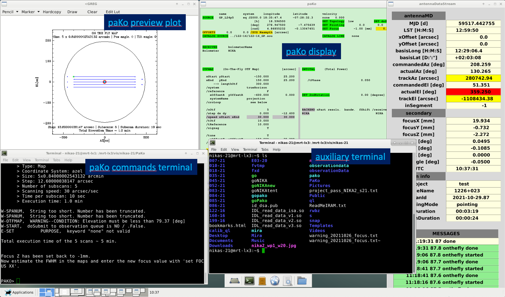
From the prompt in an auxiliary terminal in desktop 1, the observer can access the contents of the root folder of the pool account. It contains as much as folders labeled in the form XXX-YY as projects are scheduled. This is a unique identification format provided by the IRAM’s Project Management System and coincides with the account name of the project. Inside each project folder, the observer will find, at least (i) a setup file (setup*.pako), (ii) a source file (*.sou), (iii) the observing script(s) (*.pako), and (iv) a text file with the project instructions for the observers (README*). In this NIKA2 Pool folder, the observer will also find a couple of wallpapers reminding most of the NIKA2 commands explained on this site. For viewing them use the command "display nika2_wp[1,2].jpg" from this auxiliary terminal. The remaining desktops of terminal mrt-remote:32 are reserved for the XEphem windows, as well as the PIIC and IDL quick-look (QL) monitors which are continuously running during the NIKA2 Pool. All of this is referred to below. Further information will be provided to the observers at the beginning of the observing sessions.
Starting paKo
In case of need, to start the paKo session for regular observations, log into the pool account "nikaw-23", open a terminal and type:
$ ssh -XY nikaw-23@mrt-lx1.iram.es
$ goNIKAnew
$ PAKO> set project [nikaw-23 or test]
$ PAKO> set dosubmit yes
Now you are ready to start observations.
Observations queue
To check what is currently in the observation's queue, open a terminal and type:
$ ssh -XY nikaw-23@mrt-lx1.iram.es
$ observationQueue &
This will open a file browser with a list of all the observation's files commanded, which are waiting to be executed by the telescope's system. To remove any observation's file from the queue, right-click on the corresponding xml file and select "delete". The display will be automatically refreshed.
Starting XEphem
XEphem is the software currently used at the IRAM 30m telescope to keep track of the position of astronomical sources in the sky. To (re)start XEphem, open a terminal and type:
$ slogin mrt-lx3
$ xephem &
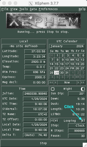
On the main Xephem window, click on the tab "RT" (for real-time) to activate source tracking in this software. Then, click on the tab "View" and open the "Sky View".
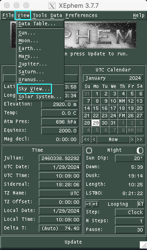
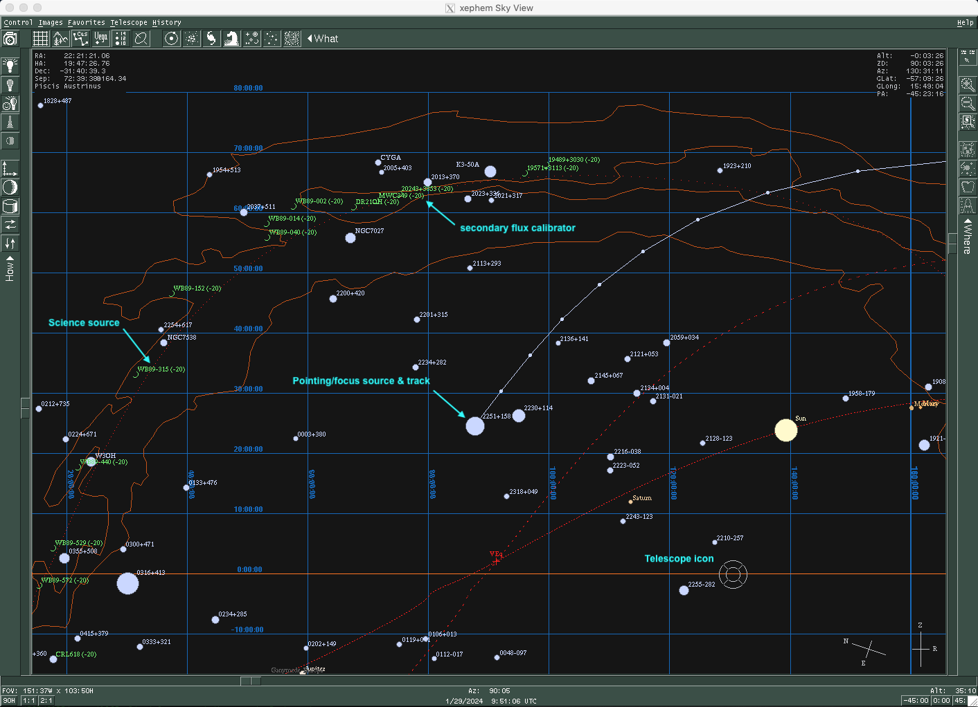
A map similar to the one shown below will appear. The "telescope icon" shows the coordinates the telescope is pointing at. The filled white circles are the pointing sources. The size of the circles is proportional to the flux of the target. Use the sliders on the border of the map for scaling the field of view.
To load the sources catalog of your project, click on the tab "Data" and go to "Files". In the new window go again to "Files" and select the catalog of the project that you plan to observe.
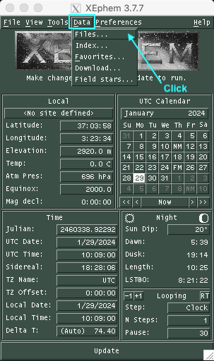

Ask the AoD or the Operator for further details.
Starting PIIC
PIIC-QL monitor has been provided to process continuously the NIKA2 data. To start it, first ask the AoD to start the production of NIKA2-imbfits required to reduce the data with PIIC.
$ ssh -XY nikaw-23@mrt-lx3
$ cd ql
$ gagpiic
$ piic @monitorX
with X = 2pf, for 2 mm-pointing/focus monitoring only, and X = 1, 2m, 3, the instrument array to be monitored.
Starting the NIKA2 IDL pipeline
Optionally, to have the IDL pipeline continuously processing observations as they are produced, open a terminal and type:
$ ssh -XY observer@nika2-a (ask the AoD for the password)
$ IDL
IDL> nk_rta, scanID    (e.g. '20201019s132')
where scanID is the corresponding identifier of the observation (as shown in the example) in the format YYYYMMDDsXXX, where YYYY is the year, MM the month, DD the day, and XXX the scan number.
Pointing
Under standard conditions, pointing corrections of the IRAM 30m telescope should be done every hour or a bit more with good stability (see below), except around dusk and dawn when more frequent pointing corrections may be necessary.
In order to correct the pointing of the telescope in a given part of the sky choose a nearby pointing source (using e.g. XEphem) and type:
PAKO> source 0133+476 /cat * (or "iram-J2000.sou" or "pointingIRAM30m.sou", or "CalibNIKA.sou" for secondary flux calibrators)
Now launch the nkpoint script:
PAKO> @ nkpoint mode
where the keyword "mode" can adopt the values b for bright sources and f for faint sources (the l option for very faint sources that require the Lissajous pattern is no longer used). To obtain the pointing corrections, use the results given by the 2pf PIIC monitor. Supplementarily, PIIC monitors 1 and 3 show the pointing corrections based on 1 mm data.
Alternatively, you can process the corresponding scan with the IDL pipeline: "IDL> nk_rta, scanID".
Once the pointing scan is processed, enter the new pointing corrections in azimuth (PnewX) and in elevation (PnewY) shown on the IDL prompt of the NIKA2 pipeline:
PAKO> set pointing PnewX PnewY
An example of PIIC-QL main plot of a standard pointing scan is shown in the following picture. Pointing correction, a proxy of the beam size (main-beam FWHM at 2 mm wavelength), and other data are highlighted:
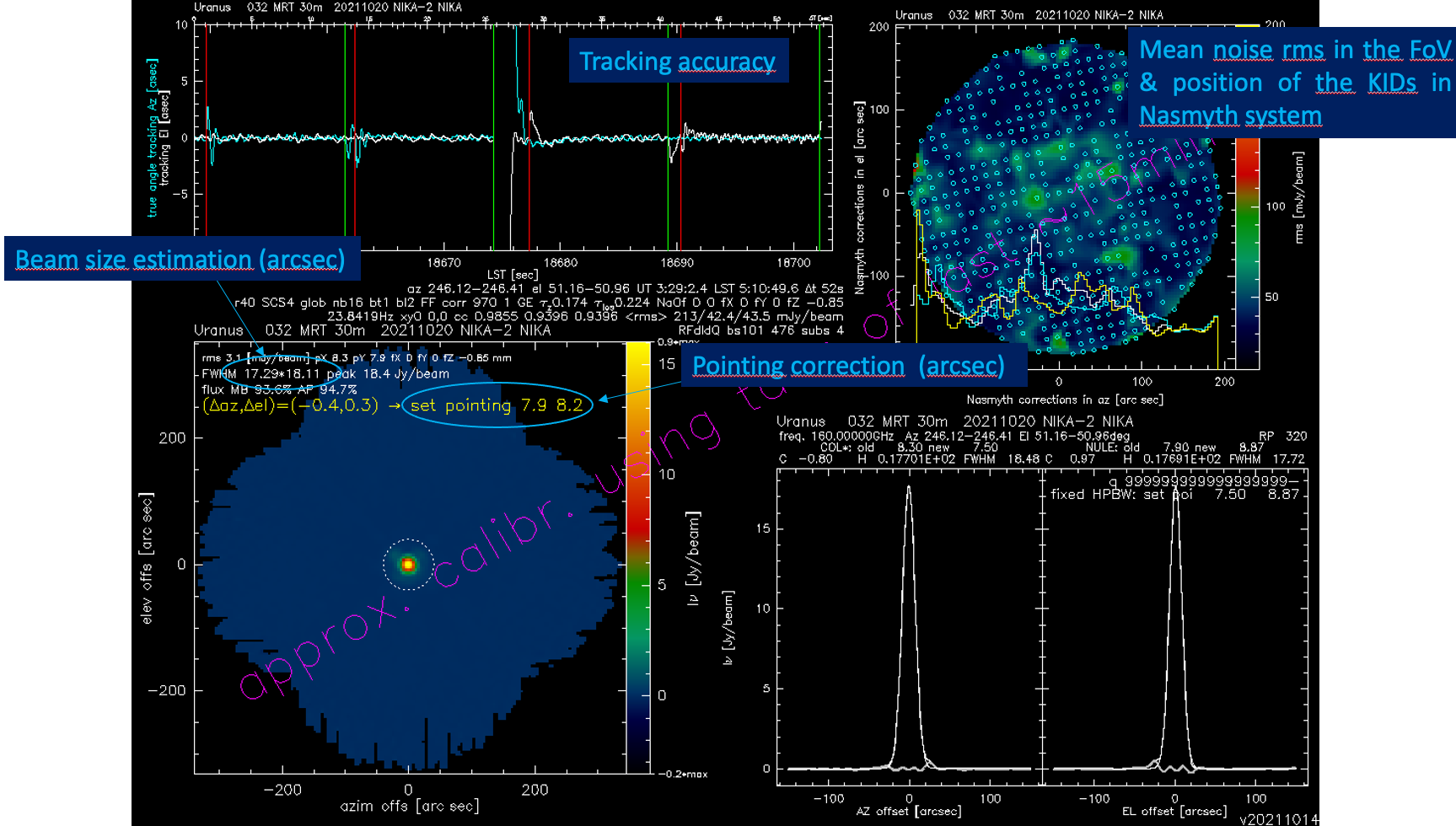
Alternatively, the corresponding pointing scan number can be processed by the IDL pipeline by simply typing:
IDL> nk_rta, scanID (in the form 'YYYYMMDDsX')
The pipeline will recognize a pointing scan and the correction will appear in a while.
According to Perotto et al. 2020, lower limits of beam size (FWHM) with NIKA2 are 11.1 arcsec (1 mm, arrays 1 & 3 combined) and 17.6 arcsec (2 mm; array 2). If you happen to have noticeable broader beam sizes, (i) probably a new focus correction would be needed, or (ii) the pointing source is not a point-like one in the sense of the main beam size, or (iii) the FWHM is measured on scans acquired in the late afternoon when the main dish of the antenna is warmed and unrelaxed, or (iv) anomalous refraction/high-frequency atmospheric instabilities could be affecting the pointing scan. In case of doubts, ask the AoD.
Focus
The focus needs to be monitored and it needs to be corrected online. This should be done every two hours or so (~3h during very stable night-time conditions, ~1h or less near sunrise and sunset) in the Z direction. To check the quality of the focus run:
PAKO> @ focusOTF-Z fz
Currently, this script will carry out 5 foci measurements in Z direction within a 1.6 mm range, centered at the fz value. Telescope focus for NIKA2 is currently around 0 to +1 mm in standard conditions. To obtain the focus corrections, use the results given by the 2pf PIIC-QL monitor. Supplementarily, PIIC-QL monitors 1 and 3 also show focus corrections from 1 mm data. It gives the best focus corrections from an order-2 fitting of the observed peak flux, and two different parameters from a 2d-gaussian fit of the source used for this purpose. Under expected conditions, these values should broadly converge. If this condition is not met, the average of the two mutually consistent values could be adopted as a focus correction. An example of a typical result of a focus sequence from the PIIC-QL monitor (2 mm) looks as follows:
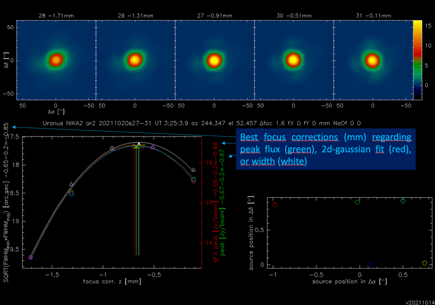
Conversely, if the fz value is not a good pivot for the focus sequence or under stable weather conditions, the focus results would be like the plots in the figures below:
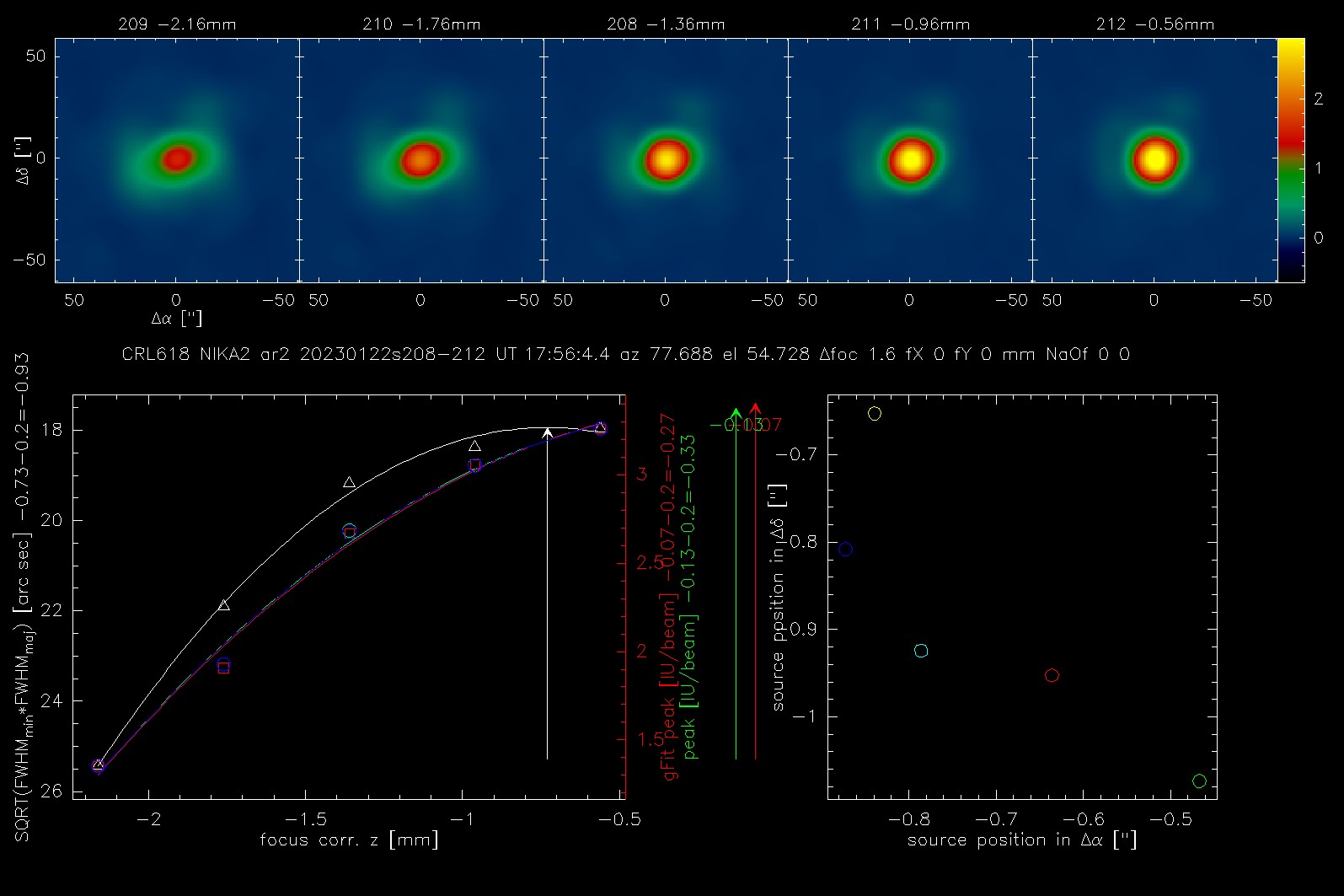
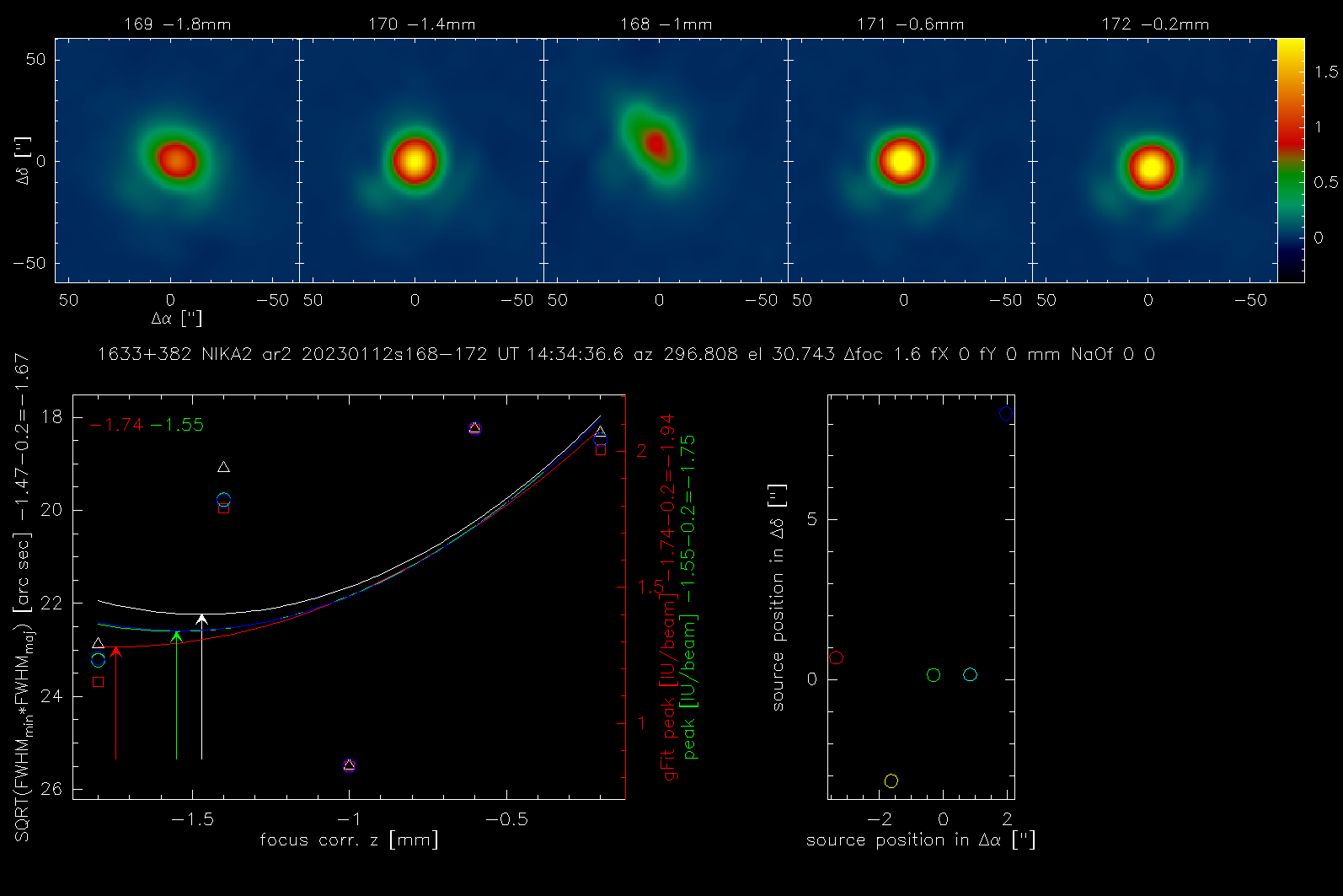
In general, after applying the new corrections, good fitting results are expected, but it is always safe to repeat pointing and focus observations once again to confirm whether the beam geometry is properly measured.
Alternatively, the corresponding scan number can be processed by the IDL pipeline:
IDL> nk_rta, scanID1    (for measurement 1)
IDL> nk_rta, scanID2    (for measurement 2)
IDL> nk_rta, scanID3    (for measurement 3)
IDL> nk_rta, scanID4    (for measurement 4)
IDL> nk_rta, scanID5    (for measurement 5)
Then, all measured foci need to be processed together by the "nk_focus_otf" routine of the IDL pipeline to perform the best focus fit in terms of the measured Flux, beam FWHM, and beam ellipticity of the KID's. This can be achieved by running the following instruction in the IDL prompt:
IDL> nk_focus_otf,'YYYYMMDDs'+strtrim(SCANNUMBER+indgen(5),2)
where the ScanID is in the format YYYYMMDDsSCANNUMBER (e.g. '20151019s132'). Once the "nk_focus_otf" routine has finished, check the focus correction values displayed in the IDL prompt under "Fluxes" for the three arrays (A1, A2, & A3) and calculate the average value that will be used to correct the focus. Enter the new focus value (Fnew) as follows:
PAKO> set focus Fnew
Daily calibrations
Beam maps
This kind of scan is to be done once a day or every two days. It takes ~25 min, so to avoid accounting for the time spent on your project think about changing the project to:
PAKO> set project nikaw-23
Beam maps are designed to ensure the source is moved over all the detectors of the array, in order to characterize and calibrate them (field of view geometry, flat field, stability, etc). The aim is to calculate the actual pixel offsets in the focal plane (see figure below). Low opacity and good stability are mandatory, and Uranus, Mars (if apparent size is < 10”), or 0316+413 (3C83) can be used for that. To obtain a beam map go to a primary calibrator, get focus/pointing corrections, and launch the beammap1scan99sub.pako script in the normal paKo session:
PAKO> @ beammap1scan99sub  (to produce 99 sub-scans, standard paKo version)
OPTION = a   (ENTER OPTION: a = Az. scan, e = El. scan, l = lower than 60° in El., h = between 60° and 70° in El.)
W-OTFMAP       /TOTF,  value 12.0 implies /speed 65.0 outside standard range 0.0 to 60.0
W-OTFMAP,  WARNING--CONDITION: Elevation must be less than 69.03 [deg]
OTFMAP 780''x 470.4'' (step 4.8)
      > Number of subscans: 99
      > Scanning speed: 65 arcsec/sec
      > Time per subscan: 12 sec
> Execution time: 23.1 min 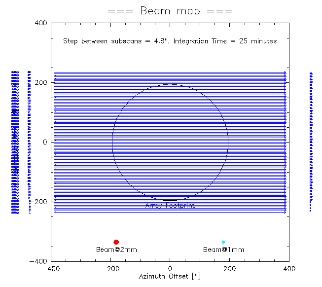
Don't forget to set back to your project once the beam map is done!
Flux calibration scans
If conditions are stable and the beam sizes are close to the expected values, get flux calibrations during the day and the night as possible, taking advantage from a focus sequence on primary (Mercury -when is not so close to the Sun-, Mars -if the apparent size is < ~10 arcsec-, Uranus, Neptune) or secondary calibrators (NGC7027, NGC7538, CRL2688, CRL618, MWC349, W3OH, ALFORI in the CalibNIKA.sou catalogue). The AoD will ask the observer for this kind of scan, which takes ~4 min:
PAKO> set project nikaw-23
To run a flux calibration with NIKA2, select the desired standard source and type in paKo:
PAKO> @ calib_1scan
Skydips
This kind of scan is to be done two to four times a day. It takes ~6 min, so to avoid accounting for the time spent on your project think about changing the project to:
PAKO> set project nikaw-23
To run a skydip with NIKA2 type in paKo:
PAKO> @ skydip
The script will perform 11 measurements (30 [s] tracks) at different airmasses wrt. the position Az = 180°, El = 55° in the HORIZON coordinate system. The skydip takes ~6.4 minutes to be finished.
Don't forget to set back to your project once the sky dip is done!
Science targets
Observations of science targets are performed via on-the-fly (OTF). Observers may want to scan only in Azimuth, as scan directions other than Azimuthal induce instabilities/drifts especially for NIKA2, and increased noise due to: change of airmass; reaction to telescope acceleration; coupling to electric/magnetic/acoustic signals.
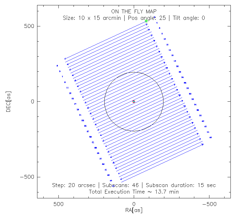
In any case, the prepared scripts allow for a variety of scanning directions. For example, for a 10'x15' OTF map, with a position angle of 25 degrees, a tilt angle of 0 degrees (both measured anticlockwise), in equatorial coordinates (radec, for the HORIZON coordinate system set azel), just type:
PAKO> @nkotf 10 15 25 0 20 40 radec
This command will produce a scan pattern as follows:
A sequence of several scans can be loaded using a script containing a sequence of nkotf maps. For example, the script observe_NGC4449.pako combines several 10'x15' OTF maps at different PA and tilt angles in the horizontal coordinate system (azel).
Note that in general, it is better to have the longer direction along the subscan to minimize the time loss due to overheads between subscans. Also for baseline subtraction in the data processing, it's always better to set a subscan length longer than the usable map you wish to have (typically ~1' more than the usable map; the optimal value depends on the map size and scanning speed). Scanning in azimuth is better for sky noise subtraction, but the best scanning strategy depends on your source shape and its az-el coverage during the integration time.
Atmosphere stability issues
At the IRAM 30m telescope the opacity at 225 GHz, tau_225GHz, is recorded by a dedicated radiometer and processed (see opacity monitor). From that, the precipitable water vapour, pwv = [tau_225GHz – 0.004]/0.058, can be estimated. These opacity estimations are plotted together with model (AM) predictions at different time scales, and they can be seen by accessing the https://weather.iram.es\opacity records & forecasts. This is a valuable tool for the observers/AoD for fine observation planning.
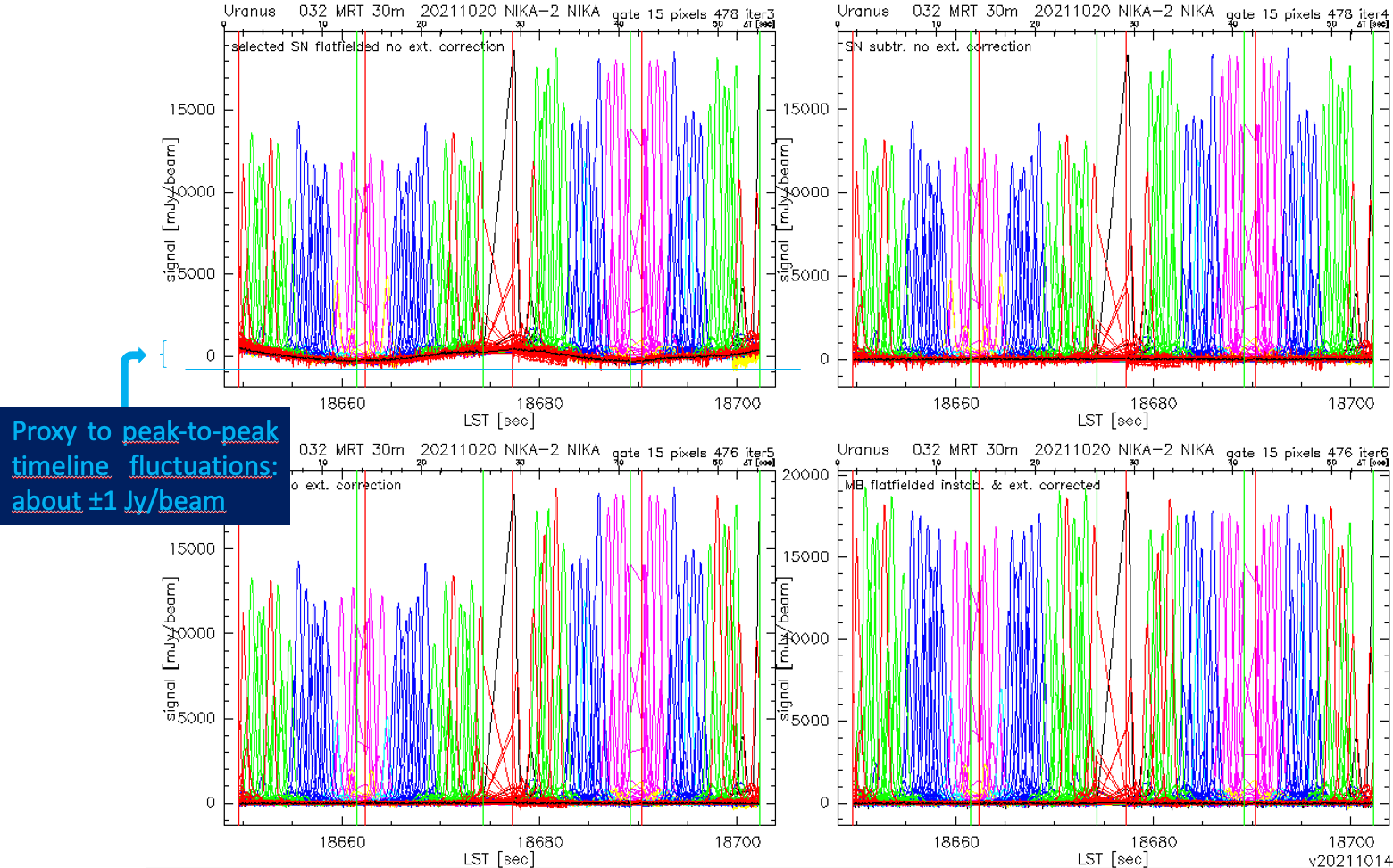
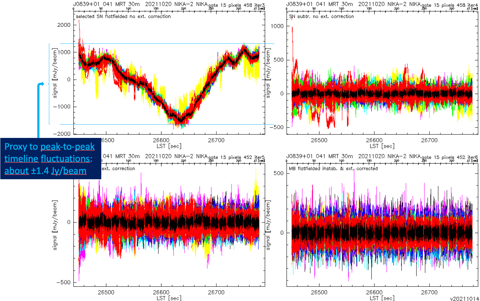
Together with opacity and the atmospheric transmission factor (modelled as exp{-tau_225GHz * sin[El.]}), the stability timescale of the atmosphere during the observations affects the baseline subtraction and the mean rms noise of a given scan. A rule-of-thumb that the observer can use as a quick approach is to have a look at the upper left plot that results from the PIIC-QL pipeline at 2 mm. As an empirical rough approach, if peak-to-peak variations of the timelines given in such a plot are below +/- ~6 Jy/beam, we can say that the atmosphere is stable in the sense of NIKA2 scan. For each project, a prescription about this issue is usually provided by the PIs of the projects to the observers. For the latter ones, it is a good practice to provide an estimation of the p2p variations, and complementarily the rms of the raw timelines, for selected scans in the logsheet of TAPAS. If we translate this rule to the 1 mm array, the threshold of these variations is -in general, but not always- about a factor 3 the value used for the 2 mm band. The following PIIC-QL plots are representative of high atmosphere stability. The first one corresponds to a scan for a pointing correction, and the second one to a science scan:
Contact: Angel Bongiovanni, Ioannis Myserlis, Stergios Amarantidis (NIKA2 NIKA2 Pool Management)
email: bongio@iram.es, imyserlis@iram.es, samarant@iram.es
Created: 2013.OCT.25, by Isreal Hermelo
Updated: 2017.FEB.05, by Pablo García
Updated: 2017.SEP.28, by Alessia Ritacco
Updated: 2017.OCT.23, by Samuel Leclercq
Updated: 2019.JAN.23, by Carsten Kramer
Last update: 2024.FEB.06, by Angel Bongiovanni
