|
Size: 241
Comment:
|
← Revision 5 as of 2016-12-11 09:55:36 ⇥
Size: 827
Comment:
|
| Deletions are marked like this. | Additions are marked like this. |
| Line 4: | Line 4: |
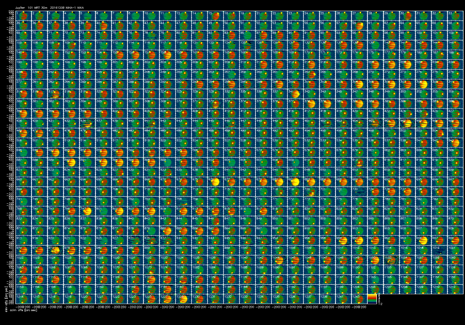
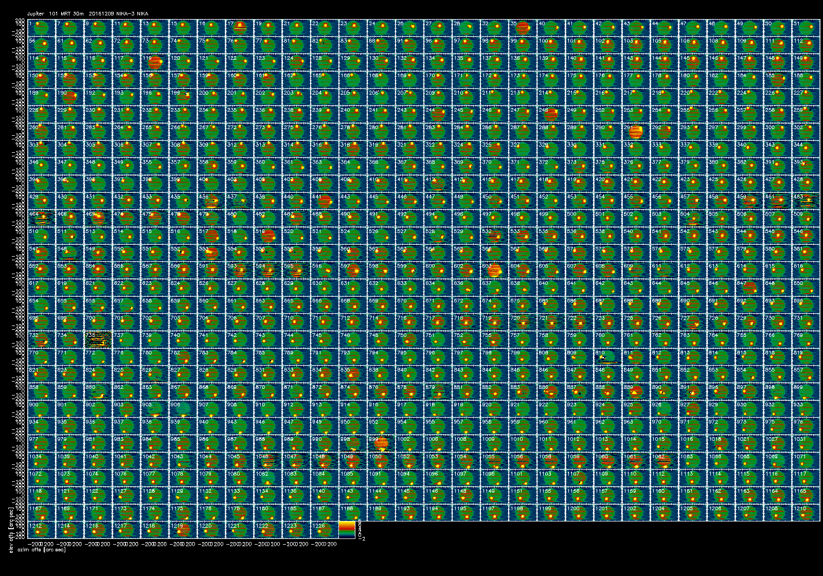
| The figure below shows the signal of the 2mm array (ar2) in % of the Jupiter peak. | The figures below shows the signal of all arrays in % of the Jupiter peak. |
| Line 6: | Line 6: |
| {{attachment:Jupiter_NIKA-2-20161209s101.png||height=800}} | {{attachment:Jupiter_NIKA-2-20161209s101.png||height=900}} {{attachment:Jupiter_NIKA-1-20161209s101.png||height=900}} {{attachment:Jupiter_NIKA-3-20161209s101.png||height=900}} Alessandro. Interesting. In particular to see that you confirm that the footprint is the whole array and not a single readout line. This is (again) a bit surprising to me. 1000 pixels seeing 1% each makes 10 times higher than the source itself. If it was the optics so we would have to admit that we absorb in the main beam less than 10% of the total. I would have preferred to see a slice of the array, and attribute this to a change in the readout line impedance. |
The "plateau".
The Jupiter map 20161209s101 allows to estimate the level of the "plateau". The figures below shows the signal of all arrays in % of the Jupiter peak.


Alessandro. Interesting. In particular to see that you confirm that the footprint is the whole array and not a single readout line. This is (again) a bit surprising to me. 1000 pixels seeing 1% each makes 10 times higher than the source itself. If it was the optics so we would have to admit that we absorb in the main beam less than 10% of the total. I would have preferred to see a slice of the array, and attribute this to a change in the readout line impedance.
