GISMO run #5 (March 2012): new optics and permanent position
Staffing of the test run
- GSFC: J. Staguhn, D. Fixsen, A. Kovacs, S. Maher, E. Sharp,
- IRAM: S. Leclercq, IRAM Granada staff
Test run schedule: 02.03. - 12.03.2012
IRAM 30m schedule page: http://www.iram.fr/IRAMFR/PV/sche/12/s09v1.html
GISMO does not appear with an explicit project number because the idea is to take up to 20 hours of the telescope time on the heterodyne pool (project 440-11). The decision for the time slots allocated to GISMO will be taken in real time (few to several hours in advance) through discussion between the GISMO team and the pool manager, based on observiong pool constraints (e.g. LST) and weather conditions.
Summarized schedule of the run:
Dates |
Main event |
Before 01.03. |
Arrival of GISMO hardware at the telescope |
02.03. Friday |
Arrival of ES, SM and DF at the telescope, start mounting GISMO in the workshop |
05.03. Monday |
Arrival of JS, AK and SL at the telescope, GISMO cooled down |
07.03. Wednesday - 11.03. Sunday |
GISMO on sky slots (up to 20 hours total). DF takes plane on Fri 09.03. |
More details on schedule, people, organization, hardware, and test plan: GISMO-On_Sky_Test_Plan_2012_v2.pdf
GISMO final version
Same 8x16 pixels as 2nd to 4th runs, working at 2mm (the –3dB window is 140-162 GHz), with an individual pixel size = 0.9 Fλ.
Same special features from previous runs: 2 motorized neutral density filters, controllable shutter, automated observing procedures usable via a dedicated GUI (see observer's manual), CRUSH reduction package.
- New updates: cold baffle, final position in the receiver cabin with corresponding warm optics.
Daily reports
Friday 02 March - Sunday 05
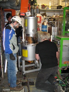
Elmer, Steve and Dale arrived at the telescope, and start mounting GISMO, then cool it down.
Monday 05 March
Johannes and Samuel arrived at the telescope. GISMO was close to base temperature. Water on the entrance window of the big baffle. Blow boil off nitrogen to it, then just use a fan. Look at the sky through the open window. Nice IV curves even without neutral density filter ==> very good sign that there's much less stray light than last year, so sensitivity should improve...
Tuesday 06 March
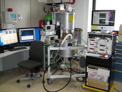
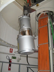
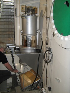
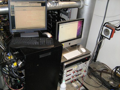
The installation of GISMO into the receiver cabin took most of the day and part of the night: check measurements and installation plan, built a crate, machine the shelve, etc., install the shelve first. Then in the afternoon move GISMO and all the other parts up in the cabin, and start mounting. Plug the electronics: few things to adjust but everything looks fine in the end. Some small offset in positions (less then 2.5cm) and orientation (less than a degree) of some of the elements. Simulate the effects of these offsets in Zemax: position offsets have almost no effect as long as the optical axis is well aligned (which we take care using the laser), angle offset very critical for the illumination of the pupil: we need a perfect alignment of the orientation of M6 toward M5; this will be done on the sky minimizing the load from the background (impossible to do it otherwise since a fraction of a degree is critical).
Wednesday 07 March
We tried to get the correct radio alignment using sky, then a hot load around M5 edges, but were not successful. 3 problems: a touch of one of the M6 rods with the bottom of the shelve, SL mistake on which rotation should be applied to M6 to optimize pupil illumination. We dismounted M6 and got the bottom of the shelve machined. Gave back the telescope. Work on a better plan for alignment, and simulations: cold pupil a bit too big, some non negligible spillover on M1 may remain even at best alignment.
Tuesday 08 March
We mounted again M6, and used correct rotations to optimize illumination minimizing background on the sky. Time to fix some incompatible pako scripts with the current system (2 backends were define in the config script), we just had the time do take our first maps on Saturn (Mars too low) and derive first pointing parameters.
Saturday 10 March
Friday was a day off (e.i. without telescope time). Saturday (Friday-Saturday night) we worked hard all night long to understand our problem of excess power on the array. The summary of the results of our test and hypothesis about what's wrong with the present situation is the following:
- When we mount GISMO at the telescope we see ~ 60K excess emission.
- Our pupil is larger than it was in Samuel's Zemax models (miscommunication on the need for a smaller pupil). This causes an over-illumination of the primary.
- However, the several cm over-illumination simulated in Zemax cannot not fully account for the observed ~60K excess. Therefore we kept searching for an explanation that would be consistent with the excess.
- We had initially been suspicious about the optical properties of M5 (the new flat mirror). However Santiago told us that the mirror quality was certified by an independent company.
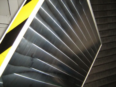
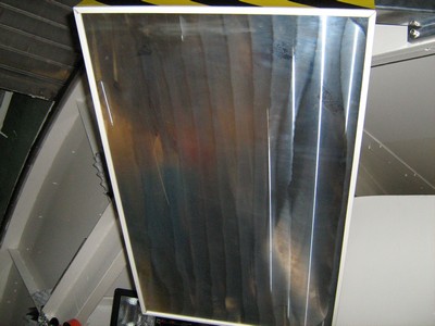
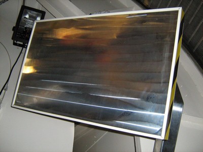
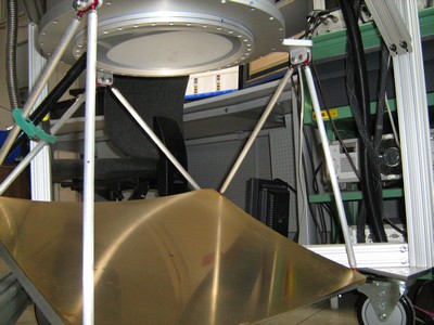
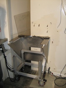
- Tonight we looked again at M5 and it became very obvious that it has large scale deformations along one axis of the surface (see pictures and movies below). So we came to suspect that these deformations have to affect the illumination of the primary.
- Samuel's Zemax simulations confirm that with the hypothesis that with a ratio of radius of curvature to size of the deformation that is equivalent to a half-pipe-shaped mirror with a 4.3 meters radius of curvature (see Zemax screen shots below), these large scale errors (we did not find a laser to measure those, will do when we have acess to the telescope again) the primary gets significantly over-illuminated, consistent with our predictions from the 60K excess. 7.We measured the pixel projections on the sky and obtain 10" pixel spacing in one direction and 19" spacing in the other (used to be 13.88" x 13.77" on sky last year). The 10" are consistent with Samuel's Zemacs calculations that use the estimated large scale structures on M5. Planets look quite crummy, even in the maps that use the measured pixel spacing on the sky.
- However, we cannot yet account for the 19"in the other direction. A concave excess in one of the mirrors could account for it. We don't know which one this might be (M5?, M6?).
- We hope we can find a way to replace M5 with a flat plate/mirror without errors. That is at the moment the only way to definitely confirm or rule-out our hypothesis that all the clues mentioned above seem to point out, and hopefully to resolve our observed image problems.
Pictures of M5:
Movies showing how the reflection of a laser moving along M5 gets distorted: MVI_1257.avi MVI_1257.avi MVI_1257.avi
Note how the diffraction line of the laser turns gently then suddenly back in original orientation then gently again and so on, other qualitative indication that the ripple structures on M5 are not sinusoids (which would have a negligible global effect as simulated on Zemax) but rather a periodic collection of half-pipes structure, compatible with a global 1D curvature as simulated on Zemax and shown on the snapshots below.
Zemax simulation snapshots (left = M5 flat / right = M5 1D curved:
Zemax_GISMO_in_cabin_2D_scheme 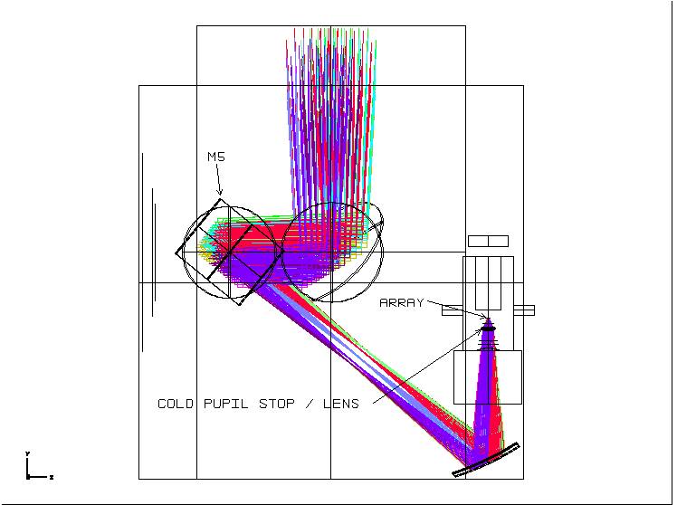
Zemax_3D_GISMO (M5 in red) 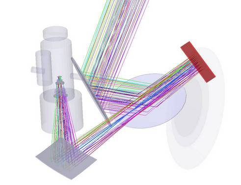
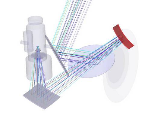
Zemax_GISMO_array
Zemax_GISMO_cold_pupil_center_field
Zemax_GISMO_cold_pupil_corner_field
Zemax_GISMO_grid_distrotion
- Remarks:
- The M5 curvature is exaggerated to 1m on the 3D drawing in order to illustrate better which axis has this equivalent curvature, but matching the Mars scan with the grid distortion gives a 4.3m equivalent radius of curvature, which is the number used to create all the other Zemax snapshots.
- Note that on the array picture the image is distorted such that the array now sees a FOV of 1.5'x4'instead of 2'x4'in the M5 flat version.
- A good cold pupil should under-illuminate the primary in order to minimize spill-over; typically a good under-illumination would appear on the cold pupil snapshots as ray traces overlapping the pupil contour like this is the case for the top-right part of the pupil_corner_field with M5 flat snapshot.

