Contents
EMIR (Eight MIxer Receiver)
Overview
The new receiver EMIR (Fig.1) has been installed and commissioned at the 30m telescope in March through April 2009. EMIR replaced the single pixel heterodyne receivers A/B100, C/D150, A/B230, and C/D270. HERA, the bolometers, and the backends are unchanged. EMIR provides a minimum instantaneous and width of 4 GHz in each of the two orthogonal linear polarizations for the 3, 2, 1.3 and 0.9mm atmospheric windows (Fig.2). In addition to the vast increase in bandwidth, the receiver is expected to offer considerably improved noise performance, a stable alignment between bands, and other practical advantages.
The four EMIR bands are designated as E090, E150, E230, and E330 according to their approximate center frequencies in GHz. While the E150 and E230 bands have SSB mixers with a single sideband available at a time, the E090 and E330 bands can be operated in 2SB mode where both sidebands are available for connection to backends. Furthermore, the E090 band is built in a technology that offers 8 GHz instantaneous bandwidth per sideband and polarization. Both polarizations of a given band will always be tuned to the same frequency as they share a single common local oscillator. The tuning ranges of the 4 bands, the typical receiver noise temperatures, and other parameters are listed in Tab.1.
EMIR provides for the first time in the history of the 30m telescope a permanently available high sensitivity E330 band, opening this atmospheric window for regular use under good weather conditions. As commissioning of this channel will be difficult and time consuming during the summer semester, proposals for the 0.9mm band of EMIR have not been considered for the March 2009 deadline. A separate Call for 0.9mm Proposals may be issued in May when the commissioning results for this highly weather dependent band will be available.
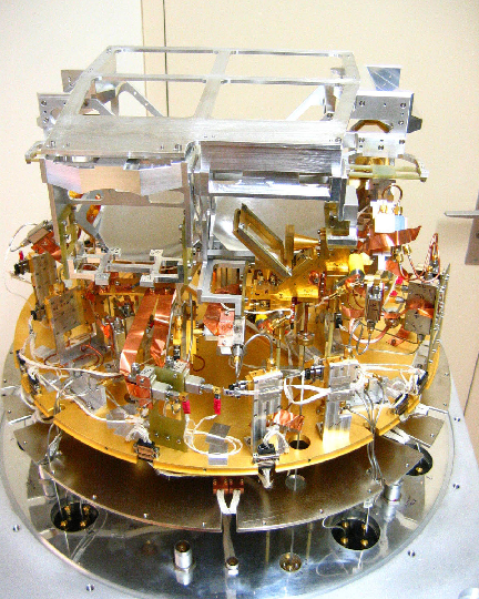
Figure 1: EMIR during final integration in the Grenoble receiver laboratory. One of the four dual-polarization mixer pairs is visible near the center of the photograph. The beams of the 4 mixer pairs leave the dewar through 4 separate windows towards the top of the figure. Warm optics (not shown) can combine some of the 4 beams for observation of the same position on the sky.
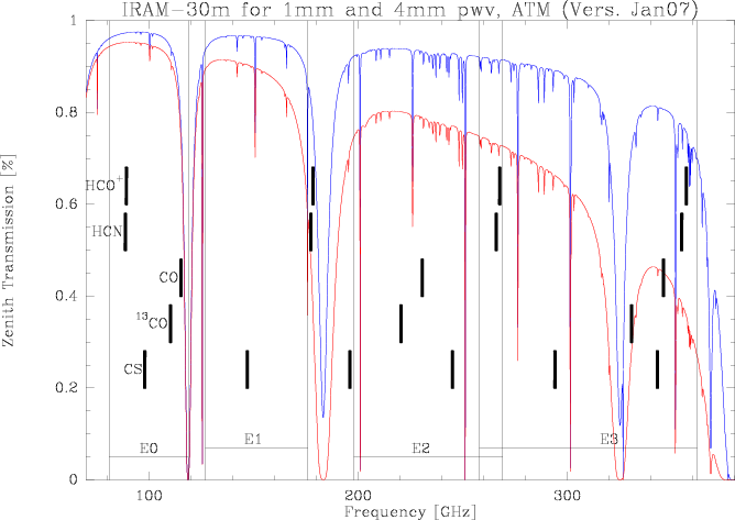
Figure 2: Atmospheric transmission between 60 and 400GHz for two precipitable water vapors, modeled with the ATM model. The EMIR bands are marked together with the frequencies of a few important molecular transitions.
Table 1: EMIR Frontend. Sky frequencies Fsky are given for the center of the IF band. 2SB dual sideband mixers, SSB - single side band mixers, H/V -- horizontal and vertical polarizations, Trx is the SSB receiver temperature in single band observations (left). For dual-band observations, Trx includes a 15K noise contribution from the dichroics (right). Changes relative to the March 09 call for proposals are marked in boldface. At the low frequency end of the 3mm band, the receiver noise temperature increases significantly to several 100 Kelvin.
EMIR |
Fsky |
mixer |
polar- |
IF width |
Trx |
Gim |
|
combinations |
Trx |
||
band |
GHz |
type |
isation |
GHz |
K |
dB |
|
E0/2 |
E1/3 |
E0/1 |
K |
E0 |
74-83-117 |
2SB |
H/V |
8 |
50 |
>10 |
|
X |
|
X |
65 |
E1 |
129.6-174 |
SSB |
H/V |
4 |
50 |
>10 |
|
|
X |
X |
65 |
E2 |
201-267 |
SSB |
H/V |
4 |
50 |
>10 |
|
X |
|
|
65 |
E3 |
260-360 |
2SB |
H/V |
4 |
70 |
>10 |
|
|
X |
|
85 |
Focal plane geometry
The four bands will be combined in only two possible beams (left and the right beams when looking to the cryostat front face). The left and right beams will be offsets by about 90" on the sky.
Left beam: E1 or E3, E1+E3 (2mm or 0.9mm, 2mm & 0.9mm)
Right beam: E0 or E2, E0+E2, E0+E1 (3mm or 1mm, 3mm & 1mm, 3mm & 2mm)
Switching between the two focal plane positions will be transparent to the user. Dual-beam observations will at present not be offered.
Selection of EMIR bands
 Before reaching the Nasmyth mirrors, the four beams of the EMIR bands pass through warm optics that contains switchable mirrors and dichroic elements for redirection of the beams towards calibration loads and for combining beams. In its simplest mode, the warm optics unit selects one single EMIR band for observation. This mode avoids the use of the slightly lossy dichroic elements and therefore offers the best receiver noise temperatures.
Three dichroic mirrors are available for combining either the E090 and E150 beams, or the E090 and E230 beams, or the E150 and E330 beams (Table 1). The combination of bands is not polarization selective, i.e. the combined bands will stay dual polarization. The small loss of these dichroics increases however the receiver temperatures by 10 - 15 K. The observer is therefore adviced to carefully evaluate whether an observation involving two different bands is more efficiently made in parallel or in series.
The dichroics are needed for dual-band observations with EMIR. The following table shows the losses of the dichroics, based on a separate mixer and dichroic characterization done in the receiver lab by Anne-Laure Fontana in Feb 09. This table is subject to change with new measurements of the integrated receiver, and with new dichroics.
Table 2: Performance of dichroics (February 2009):
E0/E2 |
E0/E1 |
E1/E3 |
|||||||||
E0 |
E0 |
E2 |
E2 |
E0 |
E0 |
E1 |
E1 |
E1 |
E1 |
E3 |
E3 |
GHz |
% |
GHz |
% |
GHz |
% |
GHz |
% |
GHz |
% |
GHz |
% |
84-108 |
2.5 |
201 |
10 |
84 |
4 |
129 |
5 |
129-138 |
2.5 |
261-357 |
<2.5 |
116 |
<2 |
213 |
5 |
92 |
3.2 |
138-156 |
1 |
147 |
4.5 |
369 |
7 |
|
|
225 |
3 |
100-116 |
5 |
168 |
2 |
156 |
3.5 |
|
|
|
|
231 |
2 |
|
|
171 |
2 |
174 |
2.5 |
|
|
|
|
243 |
5 |
|
|
174 |
2 |
|
|
|
|
|
|
255 |
5 |
|
|
|
|
|
|
|
|
|
|
267 |
50(!) |
|
|
|
|
|
|
|
|
Each percent of losses, increases the receiver temperature by about 4K.
IF Distribution
The remarkable bandwidth of EMIR of altogether 64 GHz faces 2 limitations of the existing 30m hardware: (1) the four IF cables can transport only 4 GHz each (the 4x4 GHz bottleneck) and (2) only at low spectral resolution are there enough backends to cover the 16 GHz which pass through the bottleneck.
A new IF switch box in the receiver cabin allows to select 4 EMIR channels of 4 GHz bandwidth each from 16 inputs. The 4 channels of 8 GHz width available from E090 are rearranged by the IF switch box into 4 pairs of inner and outer 4 GHz wide channels. The box can handle all plausible single band observations as well as the band combinations indicated in Table 1.
The following table shows possible band combinations with EMIR, which are allowed by the 4x4GHz bottleneck and the IF switch box (Santiago Navarro 13.2.2009):
An overview of the frequency distribution of the entire system is given in Figure 3. A total of 12 channels are input to an IF switch box, inside the receiver cabin, which allows to select 4 channels of 4GHz each to be send via the IF cables to the backends.
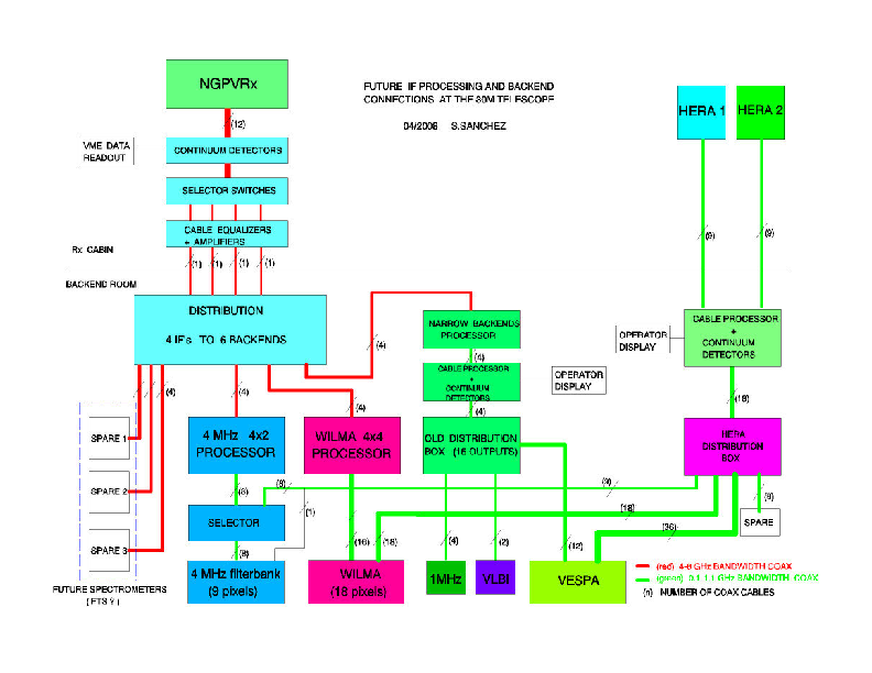
Figure 3: IF distribution
Connection to backends
The selected 4 output channels are sent via the IF cables to a new backend distribution unit which provides copies of these 4 channels to a range of backends processors which then prepare the IF signals for distribution to the spectrometers. Three new backend processors have been build to feed the new 4 GHz wide IF channels to the existing backends:
The WILMA processor rearranges the four incoming 4 GHz wide IF channels into 16 channels of 1 GHz width which can be processed by 16 WILMA autocorrelator units. Since each unit provides 512 spectral channels of 2 MHz, sufficient backend power is available at low spectral resolution for full coverage of the 4x4GHz bottleneck.
The 4 MHz processor rearranges any two incoming 4 GHz wide IF channels into 8 slices of 1 GHz width for processing in 8 units of the 4 MHz filter bank. 2x4 GHz of EMIR bandwidth are thus covered at 4 MHz resolution.
The narrow backend processor prepares the 4 incoming IF channels for input into the 1 MHz filterbank and VESPA. Only the central part of the 4 GHz IF channels is accessible to these backends. Inside this central part (1 GHz for the filterbank and 640 MHz for VESPA), these backends can be configured as before. The VLBI terminal is also fed from this processor.
Calibration issues
EMIR comes with a new calibration system. The external warm optics provides ambient temperature loads and mirrors reflecting the beams back into the 15 K stage of the cryostat. This system is expected to be very reliable and constant over time. Absolute calibration accuracy will be better than 10% with EMIR when all details are well settled.
Bands E150 and E230 have backshort tuned single-sideband mixers; DSB tuning is not possible, but sidebands (USB or LSB) may be selectable within limitations. The image rejection is better than 10 dB for all frequencies. On-site measurements of the rejection is not longer straightforward for these mixers, since the Martin--Puplett interferometers are not available anymore. As the optimum way of calibrating the image rejection is still under exploration, users who propose observations which rely on an enhanced accuracy of calibration of image gains should mention this request in the proposal.
Bands E090 and E330 have tunerless sideband separation mixers, allowing simultaneous observations of both sidebands in separate IF bands. These mixers have been characterized in the laboratory for their image rejection and are expected to have the same performance on site (>13dB).
Velocity scales
It is common practice at radio observatories to correct the frequency of an observation for the strongly time variable velocity of the Observatory with respect to the solar system barycenter. This guarantees that lines observed near the Doppler-tracked frequency, usually the band center, always have the correct barycentric velocity, independent of the time of observation. However, the effect of the Observatory's motion on the velocity scale at frequencies which are far from the Doppler-tracked frequency, is usually ignored.
This effect which is of the order of 1e-4 cannot be neglected anymore if large bandwidths are used, as with EMIR. The worst case occurs with band E090 where channels as far away as 20 GHz need to be considered if a velocity channel in one of the sidebands is Doppler-tracked. In unfavorable but nevertheless frequent cases (target source not too far from the ecliptic, like the Galactic center), errors of up to +/-2 MHz occur. Since the magnitude of the error changes with time, narrow spectral lines may be broadened after a few hours of observation.
Observers concerned by this complication may consult the dedicated section further below on this page, for further details and solutions.
Update of PaKo
The observer interface program Pako has been upgraded for EMIR. In particular, the receiver and backend commands have been adapted. Documentation is available via the help function of the new pako version. And, it will be made available in a new pako document here.
Observations time estimator
The GILDAS group has prepared a new 30m time estimator for EMIR. It is now part of the GILDAS software package and accessible via ASTRO. For download of the GILDAS package please connect to here and follow the instructions. For HERA and MAMBO2, the old web based time estimator is still available here. Note that a web based estimator for EMIR will be made available for the next deadline. As commissioning of EMIR has not yet started at the time of writing, the new time estimator is based on the laboratory performance of EMIR and the expected losses at the telescope.
FAQs
- The new ASTRO/GILDAS time estimator:
- If you have trouble installing GILDAS, we've setup accounts at IRAM/Granada and IRAM/Grenoble to allow you to login and use the ASTRO time estimator. Please contact C.Kramer or J.Pety for details.
- assumes that observations are done with both polarisations simultaneously.
- It assumes that half of the total observing time is spend observing the on and off source positions, and the other half is needed for slewing, calibration, pointing, focussing, etc.
- The time needed for tuning needs to be added by the observers, assuming 30min per tuning.
- The lower frequency limit of the 3mm LO is 91GHz. The lower band edge is 12GHz below, i.e. at 79GHz.
- WILMA can reach down to 79.5GHz. (gp, ck 4.3.09)
- VESPA can be centered in the center of one of the 4GHz bands, e.g. near 81GHz, but not lower. More precicely, VESPA can be centered 9.43GHz below the 91GHz, i.e. at 81.57GHz. And VESPA allows to cover at most +/-256MHz, i.e. 81.32 to 81.82GHz. (gp, hu, ck 4.3.09)
- VESPA:
Note that VESPA only has about 500 MHz of bandwidth. It is therefore impossible to observe simultaneously e.g. SiO (86.8 GHZ), HCO+ (89.2 GHz), and N2H+ (93.2 GHz). (ck, 27.3.2009)
- N2H+ and HCO+ 1-0 cannot be observed simultaneously with VESPA. These lines lie at 93.1733922 and 89.188523, with a difference of 3.98GHz. The centers of the outer and inner bands of E0 do *not* lie excactly at 10 and 6 GHz. Instead, they lie at 9.43 and 6.25 and are 3.18GHz apart. The maximum bandwidth of VESPA is only about +/-250MHz. (ck, 28.3.09)
- Some possible observing setups:
3mm & 1mm with 4GHz bandwidth on the sky: both polarisations, only lower sidebands, only inner 4GHz:
E0HLI, E0VLI, E2HLI, E2VLI (ra, ck, 2/3/09)3mm with 16GHz simultaneously, lower sideband in H-Pol., upper sideband in V-Pol.:
EOHLO, EOHLI, EOVUI, E0VUO
- Polarimetry: possible on a best effort basis, i.e. if the commissioning is successful. Polarimetry projects are therefore postponed to the second half of the summer semester. VESPA will be used in cross-correlation mode, as before. Phase calibrations will be done with a polarizer in front of an external cold load (hw, 10.3.2009).
For E1 (and for E2) the observer has to select the sideband to be used for both polarisations (of the same band). It is not possible to observe simultaneously e.g. the upper sideband of the H mixer and the lower sideband of the V mixer. (ck & sn, 27.3.2009)
Commissioning Report /!\ under construction /!\
- by Juan Penalver, Hans Ungerechts, Helmut Wiesemeyer, Albrecht Sievers, Gabriel Paubert, Walter Brunswig, Carsten Kramer
- and Melanie Krips, Sascha Trippe, Dirk Muders, Albert Greve, Karl Schuster
The following presentation is an excerpt from the SAC report: status30m-emir.pdf
Nasmyth Offsets
The Nasmyth offsets were determined to be -39.0"/+5.5" for the left beam and +51.0"/+5.5" for the right beam. The left beam is used for most EMIR setups, i.e. for single band E0 or E2 observations, and for dual band E0/E2 and E0/E1 observations. The right beam is used for E1, E3, E1/E3. At present, the observer has to set the Nasmyth offsets in PaKo. They are not yet set automatically when switching the EMIR setup.
Alignment
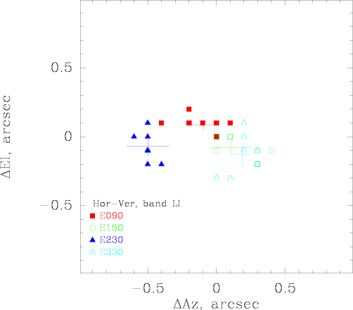
The above figure shows the alignment between the four EMIR bands and between the two polarisations of each band. The overall alignment is better than 1 arcsec.
Foci
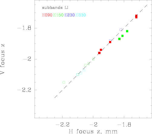
The above figure shows the focus between different polarisations of the same band. There are no significant differences between these foci.
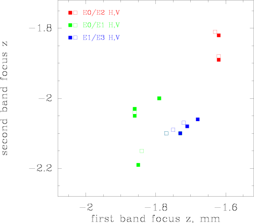
This figure shows the focus between different bands. The largest deviation is about 0.3 mm, similar to the situation with the ABCD receivers. For dual band observations, the telescope should be focussed to the high frequency band.
Telescope Efficiencies
Freq
HPBW
Feff
Beff
Aeff
S/TA*
Comments
GHz
arcsec
%
%
%
Jy/K
86
29
95
81
63
5.9
(Mars & Skydips, 4.4.09)
145
16
93
62
57
6.4
(Mars & Skydips, 4.4.09)
330
7
89
32
29
12.0
(Mars & Skydips, 4.4.09)
The main beam and aperture efficiencies, and the beam widths, were derived from Mars observations at about 43 deg Elevations, i.e. near the maximum of the gain elevation curve on March, 4th, 2009.
Spectrometers
During commissioning, we used the 4MHz filterbank and the two auto correlator backends WILMA and VESPA, partly in parallel. A variety of VESPA setups were checked, covering the range of resolutions between 3kHz and 1.25MHz and a wide range of bandwidths. VESPA parallel mode was also checked. However, it is not possible to check all possible setups. The 1MHz filterbank has not yet been commissioned.
Observing modes
The following switching modes were re-commissioned: position switching (onoff), wobbler switching, and frequency switching. Beam switching was checked using the continuum backends. The on-the-fly mapping mode was re-commissioned, in combination with position switching and with frequency switching.
Band Edges
To be done
- The 1MHz filterbank is not yet available
- HERA needs to be tested before being available again
- Polarimetry will be commissioned later
- Band 4 will be fully commissioned later
A PaKo manual is in preparation. PaKo online help on new EMIR features is already available.
Friends of EMIR
Each EMIR project of this and the forthcoming summer semester will have an IRAM astronomer assigned to it, it help with setting up the scripts and observations. See here: Friends of EMIR Projects
