|
Size: 4825
Comment:
|
Size: 5596
Comment:
|
| Deletions are marked like this. | Additions are marked like this. |
| Line 52: | Line 52: |
| The following EMIR setups were requested in the proposals for this summer semester and have been commissioned. The Code corresponds to the table created by S.Navarro describing possible setups of the switch box. | The following EMIR setups were requested in the proposals for this summer semester and have been commissioned. The Code corresponds to the table created by S.Navarro describing possible setups of the switch box. The listed Bandwidth is the total bandwidth covered by the resulting spectra, given to about 0.5GHz accuracy. |
| Line 54: | Line 54: |
| || '''Band(s)''' || '''Sidebands''' || '''Polarisations''' || '''Code''' || || E0 || 1SB || H/V || (13) || || E0 || 2SBs || one pol. || (14) || || E0/E1 || || H/V || (121) || || E0/E2 || || H/V || (131) || || E1 || || H/V || (2) || || E2 || || H/V || (3) || || E0(8GHz)/E2 || || H/V || (135) || |
|| '''Band(s)''' || '''Sidebands''' || '''Polarisations''' || '''Bandwidth''' || '''Code''' || || E0 || 1SB || H/V || 8GHz || (13) || || E0 || 2SBs || one pol. || 16GHz || (14) || || E0/E1 || 1SB || H/V || 8GHz || (121) || || E0/E2 || 1SB || H/V || 8GHz || (131) || || E0(8GHz)/E2 || 1SB || mixed || 12GHz || (135) || || E1 || 1SB || H/V || 4GHz || (2) || || E2 || 1SB || H/V || 4GHz || (3) || The following Figure shows the frequencies of the band edges and centers of the lower and upper sidebands, and the inner and outer bands. Note that the band edges and center are ''not''' exactly at multiples of 2GHz relative to the local oscillator. This is due to the IF distribution. The backends are centered near the band centers. VESPA is centered at 6.25 or 9.43GHz. For WILMA, the inner and outer bands have 0.1GHz overlap. The inner band runs from 4.125 to 7.845GHz. The outer band runs from 7.835 to 11.555GHz. {{attachment:emir3mmsetup.png}} |
DRAFT Version of EMIR Commissioning Report
Carsten Kramer with contributions from Juan Penalver, Clemens Thum, Hans Ungerechts, Helmut Wiesemeyer, Albrecht Sievers, Gabriel Paubert, Walter Brunswig, Melanie Krips, Sascha Trippe, Dirk Muders, Albert Greve, Karl Schuster
Related documents: EMIR Installation report by Santiago Navarro et al.
Nasmyth Offsets
The Nasmyth offsets were determined to be -39.0"/+5.5" for the left beam and +51.0"/+5.5" for the right beam. The left beam is used for most EMIR setups, i.e. for single band E0 or E2 observations, and for dual band E0/E2 and E0/E1 observations. The right beam is used for E1, E3, E1/E3. At present, the observer has to set the Nasmyth offsets in PaKo. They are not yet set automatically when switching the EMIR setup.
Alignment
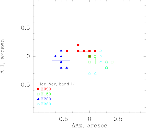
The above figure shows the alignment between the four EMIR bands and between the two polarisations of each band. The overall alignment is better than 1 arcsec.
Foci
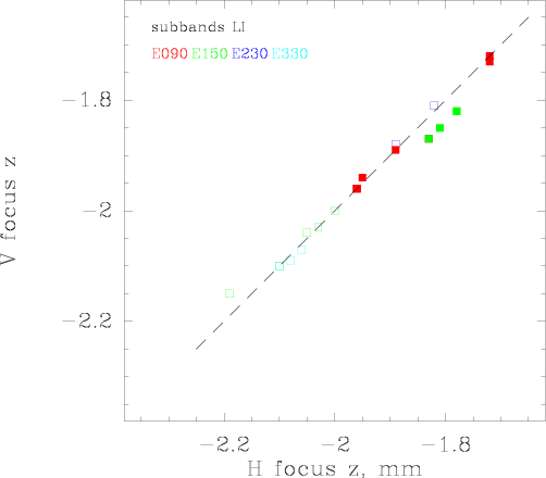
The above figure shows the focus between different polarisations of the same band. There are no significant differences between these foci.
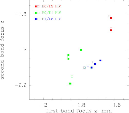
This figure shows the focus between different bands. The largest deviation is about 0.3 mm, similar to the situation with the ABCD receivers. For dual band observations, the telescope should be focussed to the high frequency band.
Telescope Efficiencies
Freq
HPBW
Feff
Beff
Aeff
S/TA*
Comments
GHz
arcsec
%
%
%
Jy/K
86
29
95
81
63
5.9
145
16
93
62
57
6.4
330
7
89
32
29
12.0
The main beam and aperture efficiencies, and the beam widths, were derived from Mars observations at about 43 deg Elevations, i.e. near the maximum of the gain elevation curve on March, 4th, 2009. The forward efficiencies were derived from Skydips. The ellipticity of the beams is better than 90% in all cases.
Continuum backends
At present, only the central 1GHz of each 4GHz chunk are being used for continuum detection. Broad band 4GHz wide continuum detectors are in preparation.
Spectrometers
During commissioning, we used the 4MHz filterbank and the two auto correlator backends WILMA and VESPA, partly in parallel. A variety of VESPA setups were checked, covering the range of resolutions between 3kHz and 1.25MHz and a wide range of bandwidths. VESPA parallel mode was also checked. However, it is not possible to check all possible setups. The 1MHz filterbank has not yet been commissioned.
Observing modes
The following switching modes were re-commissioned: position switching (onoff), wobbler switching, and frequency switching. Beam switching was checked using the continuum backends. The on-the-fly mapping mode was re-commissioned, in combination with position switching and with frequency switching.
EMIR setups
The following EMIR setups were requested in the proposals for this summer semester and have been commissioned. The Code corresponds to the table created by S.Navarro describing possible setups of the switch box. The listed Bandwidth is the total bandwidth covered by the resulting spectra, given to about 0.5GHz accuracy.
Band(s)
Sidebands
Polarisations
Bandwidth
Code
E0
1SB
H/V
8GHz
(13)
E0
2SBs
one pol.
16GHz
(14)
E0/E1
1SB
H/V
8GHz
(121)
E0/E2
1SB
H/V
8GHz
(131)
E0(8GHz)/E2
1SB
mixed
12GHz
(135)
E1
1SB
H/V
4GHz
(2)
E2
1SB
H/V
4GHz
(3)
The following Figure shows the frequencies of the band edges and centers of the lower and upper sidebands, and the inner and outer bands. Note that the band edges and center are not exactly at multiples of 2GHz relative to the local oscillator. This is due to the IF distribution. The backends are centered near the band centers. VESPA is centered at 6.25 or 9.43GHz. For WILMA, the inner and outer bands have 0.1GHz overlap. The inner band runs from 4.125 to 7.845GHz. The outer band runs from 7.835 to 11.555GHz.

Band Edges
Commissioning observations
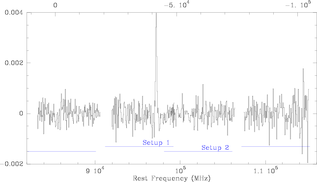
- The following figure shows a spectrum of Orion IRc2 covering 32GHz of the 3mm window. It was taken with WILMA in wobbler switched mode in two EMIR setups in 30minutes of on+off observing time. Each EMIR setup used 16GHz simultaneously, both sidebands, with one polarisation. One broken WILMA unit was later repaired. The 4MHz/8GHz Filterbank was used in parallel, but data are not shown here.
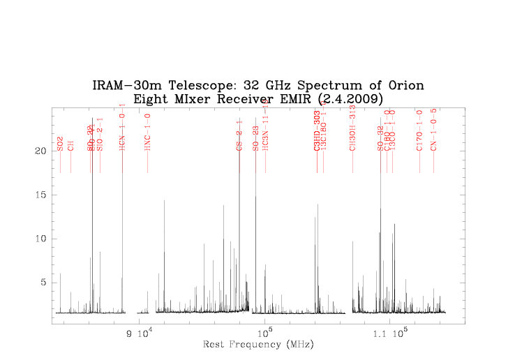
- A long 4 hour integration of the Cloverleaf, a quasar at high redshift, in the 3mm window, resulted in flat baselines with 0.4mK at 150km/s resolution. For this, we used WILMA in wobbler switching mode. The redshifted CO 3-2 line is confirmed.
To be done
- The 1MHz filterbank is not yet available
- HERA needs to be tested before being available again
- Polarimetry will be commissioned later
- Band 4 will be fully commissioned later and is in general not available this summer semester.
A PaKo manual is in preparation. PaKo online help on new EMIR features is already available.
