|
Size: 9014
Comment:
|
Size: 8952
Comment:
|
| Deletions are marked like this. | Additions are marked like this. |
| Line 1: | Line 1: |
| #acl hermelo,CarstenKramer,NicolasBillot,SamuelLeclerc:read,write,delete,revert,admin Default | #acl PabloGarcia,CarstenKramer,SamuelLeclerc:read,write,delete,revert,admin Default |
| Line 100: | Line 100: |
| PAKO> source 0133+476 /cat * | PAKO> source 0133+476 /cat * (or "iram-J2000.sou" for the given catalog) |
| Line 141: | Line 141: |
| IDL> nk_focus_otf_2,'YYYYMMDDs'+strtrim(SCANNUMBER+indgen(5),2) }}} where the ScanID is in the format YYYYMMDDsSCANNUMBER (e.g. '20151019s132'). Once the "nk_focus_otf_2" routine has finished, check the focus correction |
IDL> nk_focus_otf,'YYYYMMDDs'+strtrim(SCANNUMBER+indgen(5),2) }}} where the ScanID is in the format YYYYMMDDsSCANNUMBER (e.g. '20151019s132'). Once the "nk_focus_otf" routine has finished, check the focus correction |
| Line 161: | Line 161: |
| (FOR THE X AND Y FOCUS MEASUREMENTS, THE PROCEDURE TO OBTAIN THE FINAL FOCUS CORRECTIONS NEEDS TO BE CLARIFIED: CHECKING THE RESIDUAL PLOTS BY EYE OR ADOPTING THE FOCUS CORRECTION CALCULATED BY THE IDL PIPELINE) == Beam map (needs to be updated once we have an standard procedure) == Beam maps are designed to ensure the source is moved over all the detectors of the array, in order to characterize and calibrate them (field of view geometry, flat field, stability, etc). The aim is to calculate the actual pixel offsets in the focal plane (see figure below). To obtain a beam map go to a primary calibrator and launch the '''beammap1scan99sub''' script in the normal !PaKo session or the '''beammap1scan''' script in the goPako300 version (see section '''Starting !PaKo'''): {{{ PAKO> @ beammap1scan99sub (to produce 99 sub-scans) |
(NIKA2 COLLABORATION DECIDES TO KEEP THESE VALUES TO 0. YOU DON'T NEED TO CALCULATE THEM DURING THE OPEN POOL.) == Beam map == Beam maps are designed to ensure the source is moved over all the detectors of the array, in order to characterize and calibrate them (field of view geometry, flat field, stability, etc). The aim is to calculate the actual pixel offsets in the focal plane (see figure below). To obtain a beam map go to a primary calibrator and launch the '''beammap1scan99sub.pako''' script in the normal !PaKo session or the '''beammap1scan.pako''' script in the goPako300 version (see section '''Starting !PaKo'''): {{{ PAKO> @ beammap1scan99sub (to produce 99 sub-scans, standard PaKo version) |
| Line 183: | Line 183: |
| PAKO> @ beammap1scan (to produce 140 sub-scans) | PAKO> @ beammap1scan (to produce 140 sub-scans, PaKo300 version) |
| Line 193: | Line 193: |
| == Skydips (needs to be updated once we have an standard procedure) == | == Skydips == |
| Line 221: | Line 221: |
| Contact: Pablo García ([[http://www.iram.es/IRAMES/mainWiki/Continuum/NIKA2/Main|NIKA2]] Pool Manager) email: pgarcia@iram.es |
Contact: Alessia Ritacco ([[http://www.iram.es/IRAMES/mainWiki/Continuum/NIKA2/Main|NIKA2]] Pool Manager of the 1st open pool) email: ritaccoa@iram.es |
| Line 228: | Line 228: |
Last update: 2017.SEP.28, by Alessia Ritacco |
Observing with NIKA2
Contents
Go to the NIKA2 main page.
Starting PaKo
To start the PaKo session for rgular obsevations, log into the pool account "t22" (ask the AoD/operator for the login information), open a terminal and type:
$ ssh -X t22-lx1
$ goNIKA
$ PAKO> @ini
$ PAKO> show ! v1.2.3 2014-03-31 (to confirm the correct PaKo version is being used)
$ PAKO> set doSubmit YES
Now you are ready to start observations. An alternative PaKo version for scans with more than 100 subscans can be used by starting the PaKo session with the following commands:
$ source goPaKo300
$ pakodisplay
$ pako
$ PAKO> @ini
$ PAKO> show ! v1.2.5 2016-05-18 (to confirm the correct PaKo version is being used)
$ PAKO> set doSubmit YES
Observations queue
To check what is currently in the observation's queue, open a terminal and type:
$ ssh -X mrt-lx1
$ observationQueue
This will open a file browser with a list of all the observation's files commanded, which are waiting to be executed by the telescope's system. To remove any observation's file from the queue, right-click on the corresponding xml file and select "delete". The display will be automatically refreshed.
Starting the NIKA2 pipeline
To have the IDL pipeline continuously processing observations as they are produced, open a terminal and type:
$ ssh -X observer@nika2-a (ask the AoD for the password)
$ IDL
IDL> auto_nk_rta
You will see the message:
waiting for a new file to appear...
on the IDL prompt. It is also possible to reduce the scans manually. This can be achieved by typing:
IDL> nk_rta, scanID (e.g. '20151019s132')
where scanID is the corresponding identifier of the observation (as shown in the example) in the format YYYYMMDDsXXX, where YYYY is the year, MM the month, DD the day, and XXX the scan number.
Starting XEphem
XEphem is the software currently used at the IRAM 30m telescope to keep track of the position of astronomical sources on the sky. To start XEphem, open a terminal and type:
$ ssh -X mrt-lx3
$ xephem &
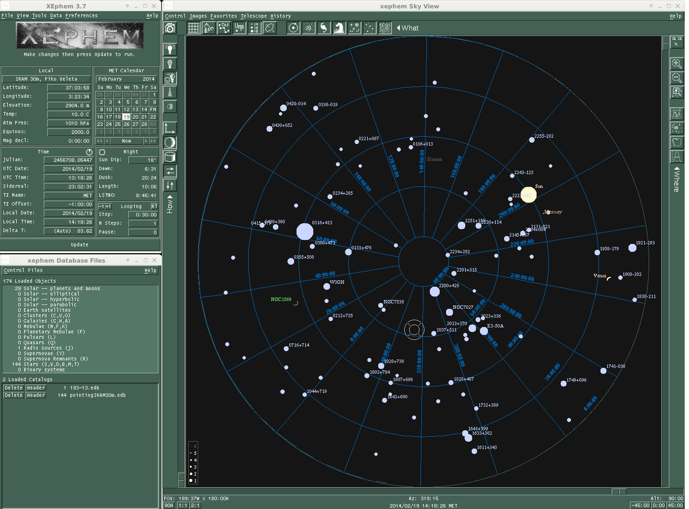
Then, click on the tab "View" and open the "Sky View". The "cross hair" shows the coordinates the telescope is pointing at. The filled blue circles are the pointing sources. The size of the circles is proportional to the flux of the target. To load the sources catalog of your project, click on the tab "Data" and go to "Files". In the new window go again to "Files" and select the catalog of the project that you are observing.

Pointing
In order to correct the pointing of the telescope in a given part of the sky choose a nearby pointing source (using e.g. XEphem) and type:
PAKO> source 0133+476 /cat * (or "iram-J2000.sou" for the given catalog)
Now launch the nkpoint script:
PAKO> @ nkpoint mode
where the keyword "mode" can adopt the values b for bright sources and f for faint sources (the l option for very faint sources that require the Lissajous pattern is no longer used). The pointing scans are currently reduced by the IDL pipeline. To obtain the pointing corrections, process the corresponding scan with the pipeline: "IDL> nk_rta, scanID". Once the pointing scan is processed, enter the new pointing corrections in azimuth (PnewX) and in elevation (PnewY) shown on the IDL prompt of the NIKA2 pipeline:
PAKO> set pointing PnewX PnewY
Focus
The focus needs to be monitored and it needs to be corrected online. This should be done every three hours or so in the Z direction and every 24 hours in the X and Y direction. To check the quality of the focus along X, Y or Z (i.e., the three axes of the subreflector), run:
PAKO> @ focusOTF-Z fz
Currently, this script will carry out 5 foci measurements in Z direction within a 1.6 mm range, centered at the fz value. In order to obtain the focus corrections, the corresponding scan number have to be processed by the IDL pipeline:
IDL> nk_rta, scanID1    (for measurement 1)
IDL> nk_rta, scanID2    (for measurement 2)
IDL> nk_rta, scanID3    (for measurement 3)
IDL> nk_rta, scanID4    (for measurement 4)
IDL> nk_rta, scanID5    (for measurement 5)
Then, all measured foci need to be procesed together by the "nk_focus_otf_2" routine of the IDL pipeline to perform the best focus fit in terms of the mesured Flux, beam FWHM, and beam ellipticity of the KID's. This can be achieved by runnning the following instruction in the IDL prompt:
IDL> nk_focus_otf,'YYYYMMDDs'+strtrim(SCANNUMBER+indgen(5),2)
where the ScanID is in the format YYYYMMDDsSCANNUMBER (e.g. '20151019s132'). Once the "nk_focus_otf" routine has finished, check the focus correction values displayed in the IDL prompt under "Fluxes" for the three arrays (A1, A2, & A3) and calculate the average value that will be used to correct the focus. Enter the new focus value (Fnew) as follows:
PAKO> set focus Fnew /dir axis
where axis is z (or x,y). The same procedure applies to the X and Y directions.
PAKO> @ focusOTF-X fx
PAKO> @ focusOTF-Y fy
(NIKA2 COLLABORATION DECIDES TO KEEP THESE VALUES TO 0. YOU DON'T NEED TO CALCULATE THEM DURING THE OPEN POOL.)
Beam map
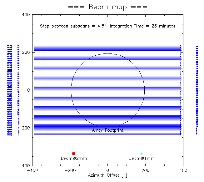
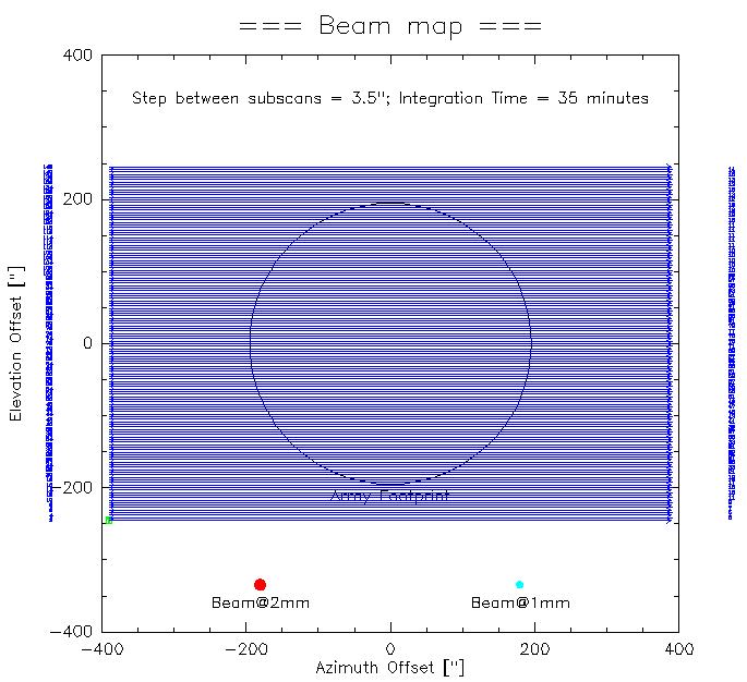
Beam maps are designed to ensure the source is moved over all the detectors of the array, in order to characterize and calibrate them (field of view geometry, flat field, stability, etc). The aim is to calculate the actual pixel offsets in the focal plane (see figure below). To obtain a beam map go to a primary calibrator and launch the beammap1scan99sub.pako script in the normal PaKo session or the beammap1scan.pako script in the goPako300 version (see section Starting PaKo):
PAKO> @ beammap1scan99sub  (to produce 99 sub-scans, standard PaKo version)
OPTION = a   (ENTER OPTION: a = Az. scan, e = El. scan, l = lower than 60° in El., h = between 60° and 70° in El.)
W-OTFMAP       /TOTF,  value 12.0 implies /speed 65.0 outside standard range 0.0 to 60.0
W-OTFMAP,  WARNING--CONDITION: Elevation must be less than 69.03 [deg]
OTFMAP 780''x 470.4'' (step 4.8)
      > Number of subscans: 99
      > Scanning speed: 65 arcsec/sec
      > Time per subscan: 12 sec
> Execution time: 23.1 min 
PAKO> @ beammap1scan (to produce 140 sub-scans, PaKo300 version)
complete beammap in a single scan with 140 subscans (use new PaKo300 from Hans !!!)
W-NOTF        /,  value 141 outside standard range 1 to 100
W-OTFMAP       /TOTF,  value 12.0 implies /speed 65.0 outside standard range 0.0 to 60.0
W-OTFMAP,  WARNING--CONDITION: Elevation must be less than 69.03 [deg]
OTFMAP 780''x 490'' (step 3.5) in 140 subscans x 12 + 2 s overheads ~= 33 min.

Skydips
To run a skydip with NIKA2 type in PaKo:
PAKO> @ skydip
The script will perform 11 measurements (30 [s] tracks) at different airmasses wrt. the position Az = 180°, El = 55° in the HORIZON coordinate system. The skydip takes ~6.4 minutes to be finished.
Science targets
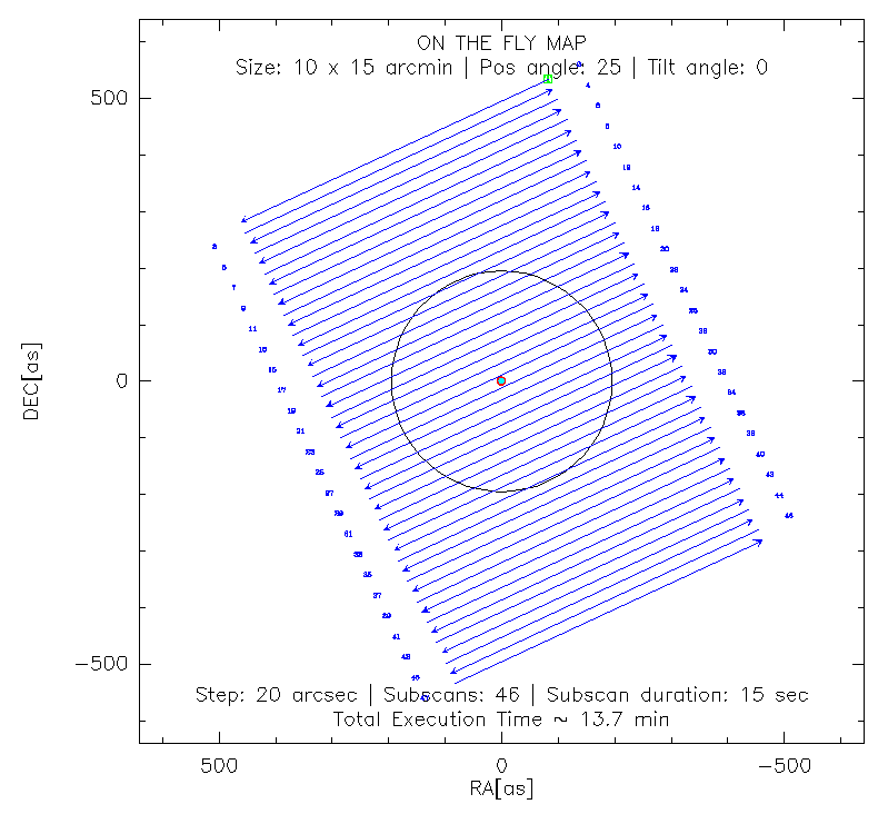
Observations of science targets are performed via on-the-fly (OTF). For example, for a 10'x15' OTF map, with a position angle of 25 degrees, a tilt angle of 0 degrees (both measured anticlockwise), in equatorial coordinates (radec, for the HORIZON coordinate system set azel), just type:
PAKO> @nkotf 10 15 25 0 20 40 radec
This command will produce a scan pattern as follows:

A sequence of several scans can be loaded using a script containing a sequence of nkotf maps. For example, the script observe_NGC4449.pako combines several 10'x15' OTF maps at different PA and tilt angles in the horizontal coordinate system (azel).
Contact: Alessia Ritacco (NIKA2 Pool Manager of the 1st open pool)
email: ritaccoa@iram.es
Created: 2013.OCT.25, by Isreal Hermelo
Last update: 2017.FEB.05, by Pablo García
Last update: 2017.SEP.28, by Alessia Ritacco
